Visualize Automated Parking Valet Using Unreal Engine Simulation
This example shows how to visualize vehicle motion in a 3D simulation environment rendered using the Unreal Engine® from Epic Games®. It closely follows the Automated Parking Valet in Simulink example.
Introduction
Automated Driving Toolbox™ integrates an Unreal Engine simulation environment in Simulink®. You can use this environment to visualize the motion of a vehicle in a prebuilt scene. This environment provides an intuitive way to analyze the performance of path planning and vehicle control algorithms. The Automated Parking Valet in Simulink example shows how to design a path planning and vehicle control algorithm for an automated parking valet system in Simulink. This example shows how to augment the model to visualize the vehicle motion in a scene using the visualization engine. The steps in this workflow are:
Create a costmap from a 3D scene.
Create a route plan from the scene.
Configure the 3D scene and ego vehicle in Simulink.
Simulate and visualize the vehicle's motion in the 3D scene.
Get a list of systems that are open now so any systems opened during this example can be closed at the end.
startingOpenSystems = find_system('MatchFilter', @Simulink.match.allVariants);Create Costmap from 3D Scene
The visualization integration comes with a number of prebuilt scenes. Each scene comes with a high-resolution image that can be used to explore the scene. Use the helperShowSceneImage function to display the images. This example uses the Large Parking Lot scene.
% Load and display the image of the parking lot
sceneName = 'LargeParkingLot';
[sceneImage, sceneRef] = helperGetSceneImage(sceneName);

% Visualize the scene image
figure
helperShowSceneImage(sceneImage, sceneRef)
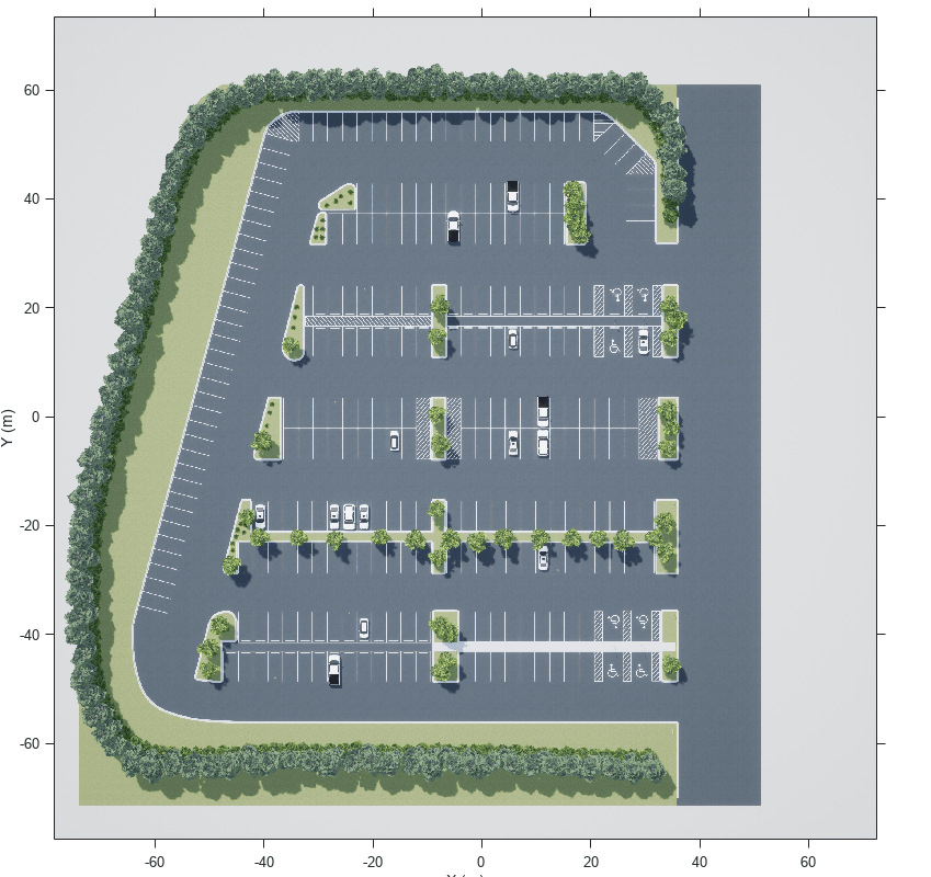
Such a high-resolution image is an accurate depiction of the environment up to some resolution. You can use this image to create a vehicleCostmap for path planning and navigation.
First, estimate free space from the image. Free space is the area where a vehicle can drive without collision with other static objects, such as parked cars, cones, and road boundaries, and without crossing marked lines. In this example, you can estimate the free space based on the color of the image. Use the Color Thresholder app from Image Processing Toolbox to perform the segmentation and generate a binary image from the image. You can also use the helper function helperCreateCostmapFromImage at the end of the example to generate the binary image:
sceneImageBinary = helperCreateCostmapFromImage(sceneImage);
Alternatively, load a pregenerated binary image.
sceneImageBinary = imread('sim3d_LargeParkingLotBinary.bmp');Next, create a costmap from the binary image. Use the binary image to specify the cost value at each cell.
% Get the left-bottom corner location of the map
mapLocation = [sceneRef.XWorldLimits(1), sceneRef.YWorldLimits(1)]; % [meters, meters]

% Compute resolution
mapWidth = sceneRef.XWorldLimits(2)-sceneRef.XWorldLimits(1); % meters
cellSize = mapWidth/size(sceneImageBinary, 2);

% Create the costmap
costmap = vehicleCostmap(im2single(sceneImageBinary), 'CellSize', cellSize, 'MapLocation', mapLocation);

figure
plot(costmap, 'Inflation', 'off');
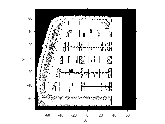
legend offYou also need to specify the dimensions of the vehicle that will park automatically based on the vehicles available in the 3D scene. This example uses the dimension of a Hatchback. These dimensions need to be consistent between the costmap and the Simulink model.
centerToFront = 1.104; % meters
centerToRear  = 1.343; % meters
frontOverhang = 0.828; % meters
rearOverhang  = 0.589; % meters
vehicleWidth  = 1.653; % meters
vehicleHeight = 1.513; % meters
vehicleLength = centerToFront + centerToRear + frontOverhang + rearOverhang;

vehicleDims = vehicleDimensions(vehicleLength, vehicleWidth, vehicleHeight,...
    'FrontOverhang', frontOverhang, 'RearOverhang', rearOverhang);
costmap.CollisionChecker.VehicleDimensions = vehicleDims;
Set the inflation radius by specifying the number of circles enclosing the vehicle.
costmap.CollisionChecker.NumCircles = 5;
Create Route Plan from a 3D Scene
The global route plan is described as a sequence of lane segments to traverse in order to reach a parking spot. You can interactively select intermediate goal positions from the scene image using the tool described in Select Waypoints for Unreal Engine Simulation. In this example, the route plan has been created and stored in a table. Before simulation, the PreLoadFcn callback function of the model loads the route plan.
data      = load('routePlanUnreal.mat');
routePlan = data.routePlan %#ok<NOPTS>
routePlan=5×3 table
           StartPose                   EndPose            Attributes
    _______________________    _______________________    __________
     44.5        8      180    -33.5      8.5      180    1×1 struct
    -33.5      8.5      180    -45.2     -0.7      250    1×1 struct
    -45.2     -0.7      250    -33.5    -13.5        0    1×1 struct
    -33.5    -13.5        0    -20.3    -13.5       -7    1×1 struct
    -20.3    -13.5       -7    -13.5     -6.8       90    1×1 struct
% Plot vehicle at the starting pose
startPose = routePlan.StartPose(1,:);
hold on
helperPlotVehicle(startPose, vehicleDims, 'DisplayName', 'Current Pose')
legend

for n = 1 : height(routePlan)
    % Extract the goal waypoint
    vehiclePose = routePlan{n, 'EndPose'};

    % Plot the pose
    legendEntry = sprintf('Goal %i', n);
    helperPlotVehicle(vehiclePose, vehicleDims, 'DisplayName', legendEntry);
    hold on
end
hold off
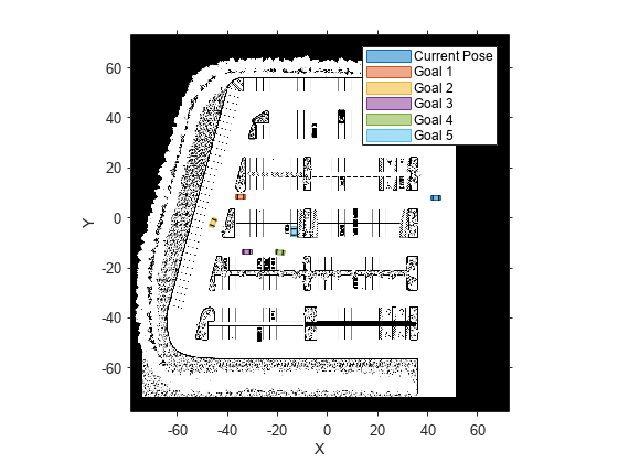
Configure 3D Scene and Ego Vehicle
Close the figures and open the model.
helperCloseFigures

if ~ispc
    error(['3D Simulation is only supported on Microsoft', char(174), ' Windows', char(174), '.']);
end

modelName = 'APVWith3DSimulation';
open_system(modelName)
snapnow
This model extends the one used in the Automated Parking Valet in Simulink example by adding two blocks for visualizing the vehicle in the 3D scene:
Simulation 3D Scene Configuration: Implements the 3D simulation environment. The Scene name parameter is set to
Large parking lot.Simulation 3D Vehicle with Ground Following: Provides an interface that changes the position and orientation of the vehicle in the 3D scene. The Type of the vehicle is set to
Hatchbackto be consistent with the vehicle dimensions incostmap. The inputs to this block are the vehicle's[X, Y]position in meters and theYawheading angle in degrees. These values are in the world coordinate system.
Visualize Vehicle Motion in 3D Scene
Simulate the model to see how the vehicle drives into the desired parking spot.
sim(modelName)
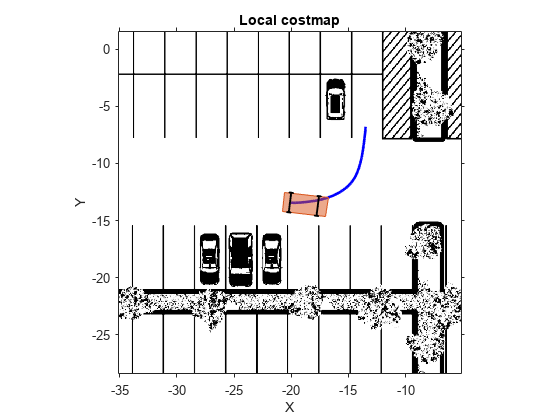
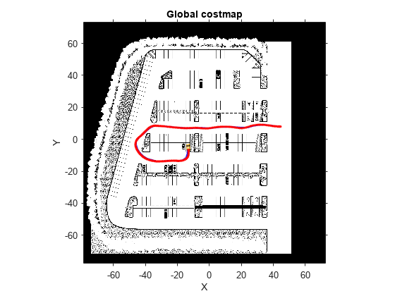
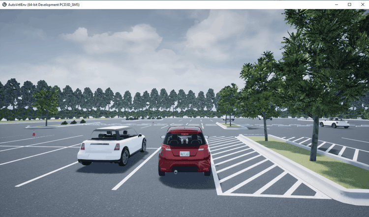
As the simulation runs, the Simulink environment updates the position and orientation of the vehicle in the 3D visualization engine through the Simulation 3D Vehicle with Ground Following block. A new window shows the ego vehicle in the 3D visualization engine. The Automated Parking Valet figure displays the planned path in blue and the actual path of the vehicle in red. The Parking Maneuver figure shows a local costmap used in searching for the final parking maneuver.
Explore Enhanced Path Planning System
The Path Planner block plans a feasible path through the environment map using the optimal rapidly exploring random tree (RRT*) algorithm. To ensure the performance of the planning algorithm, the path planning module is modified to include two separate modules:
Driving Mode: Uses the costmap of the entire parking lot for navigation. This implementation is also used in the Automated Parking Valet in Simulink example.
Parking Mode: Uses a local costmap for the final parking maneuver. The local costmap is a submap of the costmap with a square shape. To specify the size of this map, use the Local costmap size (m) parameter of the Path Planner block dialog box. A costmap with smaller dimensions significantly reduces the computation burden in searching for a feasible path to the final parking spot. It also increases the probability of finding a feasible path given the same planner settings.
Open the Path Planner subsystem.
open_system([modelName, '/Path Planner'], 'force')
The two path planner modules are implemented as Enabled Subsystem (Simulink) blocks. The enable signal is from the IsParkingManeuver signal in the input Config bus sent from the Behavior Planner block. When the Parking Mode subsystem is enabled, a local costmap is created with the center as the current position of the vehicle.
Close the models and figures.
endingOpenSystems = find_system('MatchFilter', @Simulink.match.allVariants);
bdclose(setdiff(endingOpenSystems,startingOpenSystems))
helperCloseFigures
Conclusions
This example showed how to integrate 3D simulation with the existing Automated Parking Valet in Simulink example to visualize the motion of vehicle in a 3D parking lot scene.
Supporting Functions
helperCreateCostmapFromImage
function BW = helperCreateCostmapFromImage(sceneImage) %#ok<DEFNU>
%helperCreateCostmapFromImage Create a costmap from an RGB image.

% Flip the scene image
sceneImage = flipud(sceneImage);

% Call the autogenerated code from the Color Thresholder app
BW = helperCreateMask(sceneImage);

% Smooth the image
BW = im2uint8(medfilt2(BW));

% Resize
BW = imresize(BW, 0.5);

% Compute complement
BW = imcomplement(BW);
end
helperCreateMask
function [BW,maskedRGBImage] = helperCreateMask(RGB)
%createMask  Threshold RGB image using auto-generated code from colorThresholder app.
%  [BW,MASKEDRGBIMAGE] = createMask(RGB) thresholds image RGB using
%  auto-generated code from the colorThresholder app. The colorspace and
%  range for each channel of the colorspace were set within the app. The
%  segmentation mask is returned in BW, and a composite of the mask and
%  original RGB images is returned in maskedRGBImage.

% Auto-generated by colorThresholder app on 22-Oct-2021
%------------------------------------------------------


% Convert RGB image to chosen color space
I = RGB;

% Define thresholds for channel 1 based on histogram settings
channel1Min = 42.000;
channel1Max = 179.000;

% Define thresholds for channel 2 based on histogram settings
channel2Min = 66.000;
channel2Max = 191.000;

% Define thresholds for channel 3 based on histogram settings
channel3Min = 67.000;
channel3Max = 164.000;

% Create mask based on chosen histogram thresholds
sliderBW = (I(:,:,1) >= channel1Min ) & (I(:,:,1) <= channel1Max) & ...
    (I(:,:,2) >= channel2Min ) & (I(:,:,2) <= channel2Max) & ...
    (I(:,:,3) >= channel3Min ) & (I(:,:,3) <= channel3Max);
BW = sliderBW;

% Initialize output masked image based on input image.
maskedRGBImage = RGB;

% Set background pixels where BW is false to zero.
maskedRGBImage(repmat(~BW,[1 1 3])) = 0;
end
helperCloseFigures
function helperCloseFigures()
%helperCloseFigures Close all the figures except the simulation visualization

% Find all the figure objects
figHandles = findobj('Type', 'figure');

% Close the figures
for i = 1: length(figHandles)
    close(figHandles(i));
end
end
