Sign Following Robot Using YOLOv2 Detection Algorithm with ROS in Simulink
This example shows how to use Simulink® to control a simulated robot running on a separate ROS-based simulator. It then shows how to generate CUDA-optimized code for the ROS node, from the Simulink model and deploy it to the localhost device.
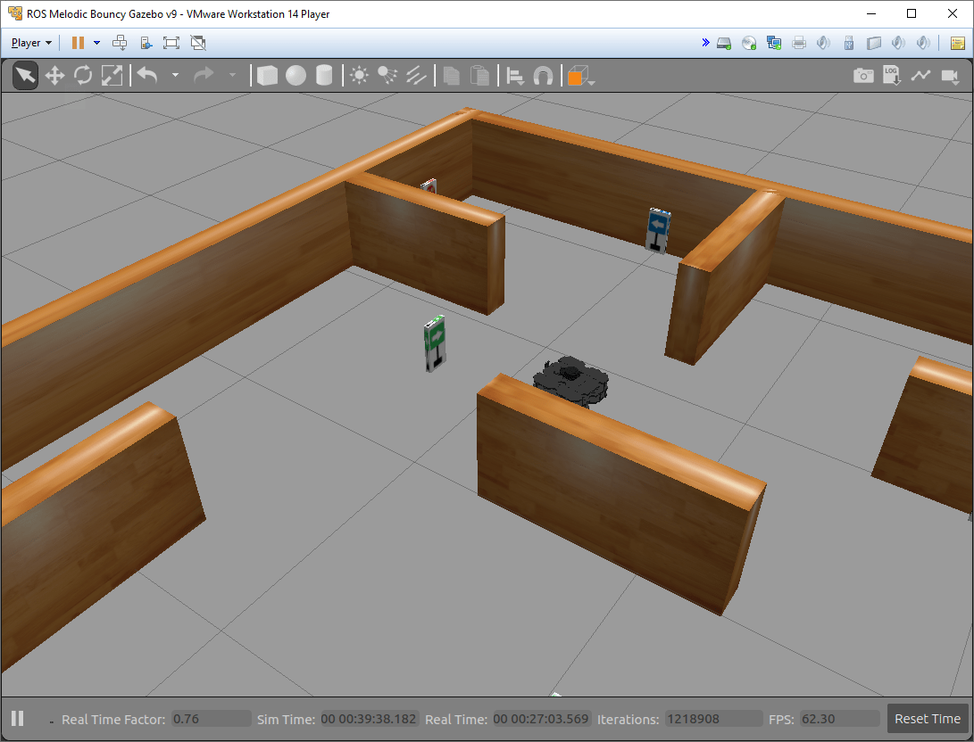
In this example, you run a model that implements a sign-following algorithm and controls the simulated robot to follow a path based on signs in the environment. The algorithm receives the location information and camera information from the simulated robot, which is running in a separate ROS-based simulator. The algorithm detects the color of the sign using a YOLO v2 detector and sends the velocity commands to turn the robot based on the color. In this example, the algorithm is designed to turn left when robot encounters a blue sign and turn right when robot encounters a green sign. Finally the robot stops when it encounters a red sign.
To see this example using ROS 2 or MATLAB®, see Sign Following Robot with ROS in MATLAB.
Start Robot Simulator
Start a ROS-based simulator for a differential-drive robot and configure the Simulink® connection with the robot simulator.
This example uses a virtual machine (VM). For instructions on downloading the virtual machine, see Get Started with Gazebo and Simulated TurtleBot.
Start the Ubuntu® virtual machine desktop.
In the Ubuntu desktop, click the Gazebo Sign Follower ROS icon to start the Gazebo world built for this example.
Get Pretrained Sign Detection Network
This function downloads the YoloV2DirectionSignRecognitionModel.mat file if is is not already present.
exampleHelperGetYoloV2DirectionSignRecognitionNetwork()
Downloading pretrained lane detection network (58b MB)...
Open Model and Configure Simulink
Setup the Simulink ROS preferences to communicate with the robot simulator.
Open the example model.
open_system('signFollowingRobotYOLOv2ROS.slx');To configure the network settings for ROS.
From Simulation tab, Prepare group, select ROS Network.
Specify the IP address and port number of the ROS master in Gazebo. For this example, the ROS master in Gazebo is
192.168.203.128:11311. Enter192.168.203.128in the Hostname/IP address box and11311in the Port Number box.Click OK to apply changes and close the dialog.
On each time step, the algorithm detects a sign from the camera feed, decides on turn and drives it forward. The sign detection is done using a pretrained YOLO v2 object detector in the Deep Learning Object Detection subsystem of the model.
open_system('signFollowingRobotYOLOv2ROS/Deep Learning Object Detection');The Sign Tracking Logic subsystem implements a Stateflow® chart that takes in the detected image size and coordinates from Deep Learning Object Detection and provides linear and angular velocity to drive the robot.
open_system('signFollowingRobotYOLOv2ROS/Sign Tracking Logic');Run the Model
Open Configuration Parameters dialog of the signFollowingRobotYOLOv2ROS model. In Simulation Target pane, select GPU acceleration. In the Deep Learning group, select the target library as cuDNN.
set_param('signFollowingRobotYOLOv2ROS','GPUAcceleration','on');
set_param('signFollowingRobotYOLOv2ROS','SimDLTargetLibrary','cudnn');
set_param('signFollowingRobotYOLOv2ROS','DLTargetLibrary','cudnn');
Run the model and observe the behavior of the robot in the robot simulator.
The video viewers show the actual camera feed and the detected sign image.
In the simulator, the robot follows the sign and turns based on the color.
The simulation stops automatically once the robot reaches the red sign at the end.

Generate and Deploy CUDA-Optimized ROS Node
Third-Party Prerequisities
CUDA enabled NVIDIA GPU.
NVIDIA CUDA toolkit and driver.
NVIDIA cuDNN library.
Environment variables for the compilers and libraries. For more information, see Installing Prerequisite Products (GPU Coder) and Setting Up the Prerequisite Products (GPU Coder).
Configure the Simulink Model for GPU code generation
Open Configuration Parameters dialog of the signFollowingRobotYOLOv2ROS model. In Hardware Implementation pane, select Robot Operating System (ROS) for Hardware Board and specify the appropriate Device Vendor and Device Type. Then, in Code Generation pane, select the Language as C++ and enable Generate GPU code.
set_param('signFollowingRobotYOLOv2ROS','TargetLang','C++');
set_param('signFollowingRobotYOLOv2ROS','GenerateGPUCode','CUDA');
In Code Generation > Libraries > GPU Code pane, enable cuBLAS, cuSOLVER and cuFFT.
set_param('signFollowingRobotYOLOv2ROS','GPUcuBLAS','on');
set_param('signFollowingRobotYOLOv2ROS','GPUcuSOLVER','on');
set_param('signFollowingRobotYOLOv2ROS','GPUcuFFT','on');
Deploy ROS Node
To configure ROS node deployment on local host machine, in the Connect section of ROS tab, set Deploy to to Localhost. Select the Build and Run button from ROS tab to deploy the node. At the end of build process, you will see the ROS node running on local host machine.
