Plan Manipulator Path for Dispensing Task Using Inverse Kinematics Designer
This example shows how to design a robotic manipulator path for a dispensing task. A successful path consists of a sequence of collision-free waypoints that are designed and verified in the Inverse Kinematics Designer app. Create waypoints for an adhesive dispensing task, in which the robot picks up two adhesive strips, applies glue, and then applies the strips to a box.
Create Robot and Environment Elements for the Scene
This example has three main steps:
The robot picks up adhesive strips from a loading station using a custom tool.
The robot places the tool under a dispensing stand, where glue is applied to both strips.
The robot attaches the two strips to the object in the desired location.
The example uses a Universal Robots UR5e manipulator, equipped with a custom end effector. The result of this application is a series of waypoints that can be connected via a planner, trajectory tooling, or both. The path planner takes the waypoints to generate a single collision-free path that reaches all the waypoints.
Create UR5e with Custom End Effector
This example will make use of the UR5 e-series, which is available in the robot library.
ur5e_robot = loadrobot("universalUR5e");Create the custom gripper with the customEEBuilder helper function and then attach the custom gripper to the robot. Show the robot to verify that the gripper is on the robot.
customEE = customEEBuilder.build(true);
addSubtree(ur5e_robot,'tool0',customEE);
show(ur5e_robot);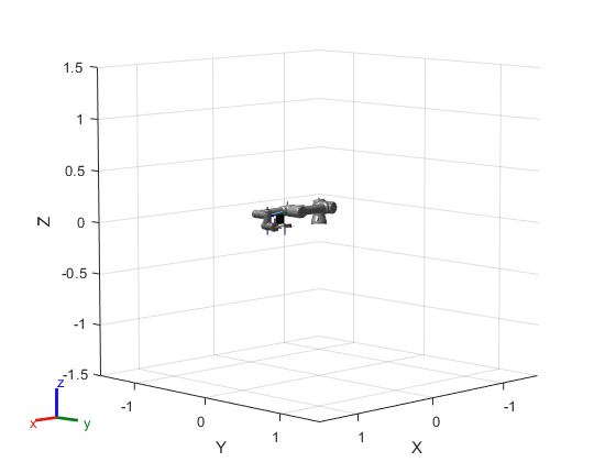
Create Environment Representation
The complete scene has several collision objects to represent scene objects. Create the primitive collision objects using the constructToolStation helper function.
Add the feeder station at the position [0 0.4 0].
stationPose = trvec2tform([0 0.4 0]);
[toolStationBase,partFeeder] = constructToolStation(stationPose);
Next add the dispensing station, modeled by a small cylinder next to the feeder at [.25 .45 .65].
dispensingStation = collisionCylinder(.01,.1);
dispensingStation.Pose = trvec2tform([.25 .45 .65]);
Create a platform underneath the robot located at [0 0 -.011].
platform = collisionBox(1,1,0.02);
platform.Pose = trvec2tform([0 0 -.011]);
Add the box that the robot places adhesive strips on in front of the robot at [0.3 -.3 .05].
box = collisionBox(0.2,0.3,0.1);
box.Pose = trvec2tform([0.3 -.3 .05]);
Use Inverse Kinematics Designer to Create Waypoints
Use Inverse Kinematics Designer to find the waypoint configurations that satisfy specific goals. Once the waypoints are created, these configurations are exported from the app to the base workspace.
To skip to the final state, load the included save session dispensingSessionData and that associated exported configurations by executing:
inverseKinematicsDesigner("dispensingSessionData.mat")
load pathWaypointData.mat
Otherwise, follow along with the example.
Start New Session
Now that the scene elements have been defined, start a new app session and populate it with the robot and environment pieces.
To start the app, open it from the Apps ribbon, or call it using the following command:
inverseKinematicsDesigner
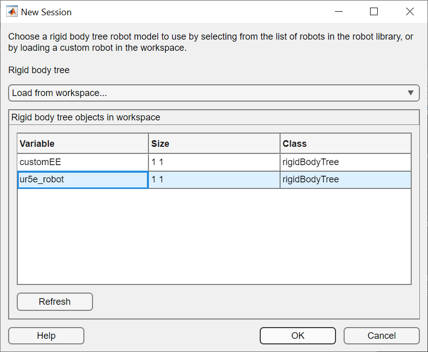
Next, start a new session. On the toolstrip, click New Session to bring up the New Session dialog box. Make sure the dropdown is set to Load robot from workspace and select ur5e_robot, the robot that was defined in the previous section. Click OK to import it and start the session.
Add Environment to Scene
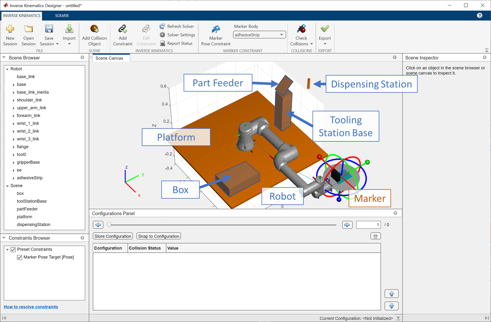
To load the environment model, click Scene > Add Collision Object in the Inverse Kinematics tab. This will bring up the Add Collision Object dialog, which shows all the available collision objects in the MATLAB® workspace. Shift-click to select the box, dispensing station, tool station base, part feeder, and platform.
Click Add to add these objects to the scene. Then use the Axes Toolbar on the figure in the Scene Canvas to reposition to scene so it fits. See Use Scene Canvas and Move Robot for more information.
The Inverse Kinematics Designer session is now set up, containing the scene elements and robot, which can be interactively guided by the marker.
Add Waypoints for Each Task
Find the configurations that correspond to the waypoints for each task. Constraints will be used along the way to ensure that each configuration satisfies the target pose.
Pick up the Adhesive Strips from the Part Feeders
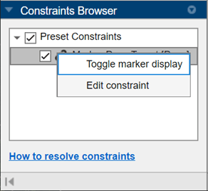
The two flat panels simulation adhesive grip attachments on the gripper must align with the pads at the feeding station. To see these parts, it is helpful to temporarily disable the marker visuals. Right-click on the Marker Pose Constraint in the Constraints Browser and select Toggle marker display to disable the marker visuals.
Now click on partFeeder in the Scene Browser. To ensure the parts are properly picked, the goal will be to place the modeled attached strip on the gripper so that it aligns with the part feeder. Read the pose of the object from the scene inspector. The object is located at [-.05 .4 .525] and rotated 45 degrees about the world X axis.
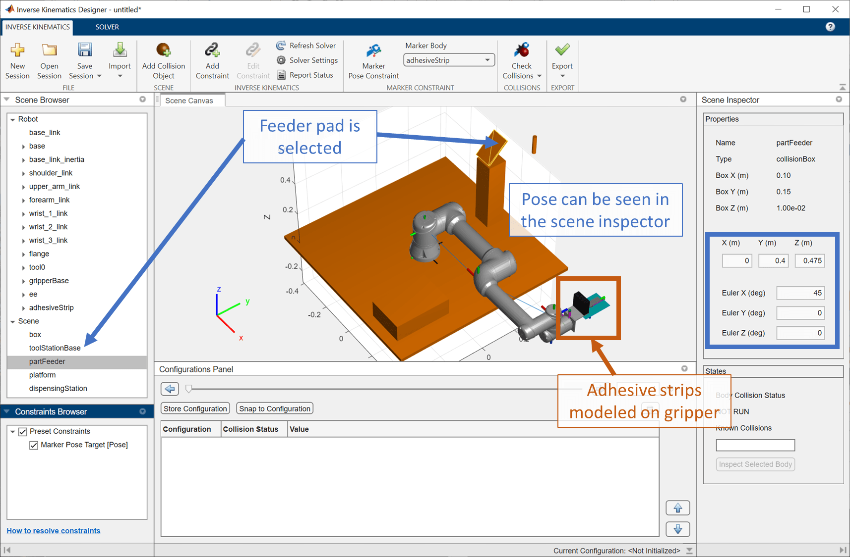
Move marker pose target to this pose so that a configuration is found in which the robot is aligned in the picking task pose. While it could be possible to achieve this via hand tuning, the most direct way is to directly set the end effector pose. Click on Marker Pose Constraint in the toolstrip, or alternatively select the Marker Pose Constraint in the Constraints Browser and selecting Edit Constraint. Once the constraint appears in the toolstrip, enter the pose of the object, [-.05 .4 .525] and rotated 45 degrees about the world X. As each value is added, the pose axis visual preview in the scene updates to indicate the new target pose.
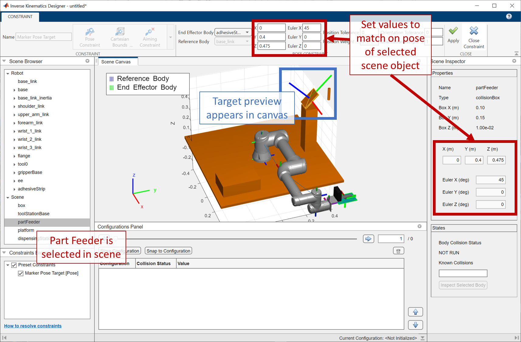
Click Apply in the Constraint tab to set this value as the target. This updates the pose, but the robot is backwards from the intended direction. Set Euler Y to 180 to add a rotation of 180 degrees about the Y axis to flip the target pose.
The necessary orientation of the end effector can be determined ahead of time by examining the gripper.
show(customEE);
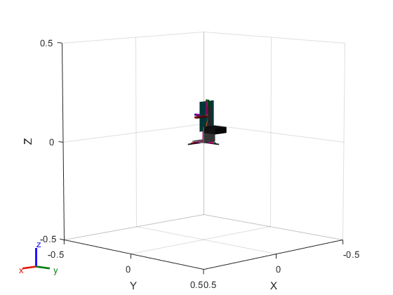
Select the adhesive strip to highlight the orientation of its origin and reference frame.
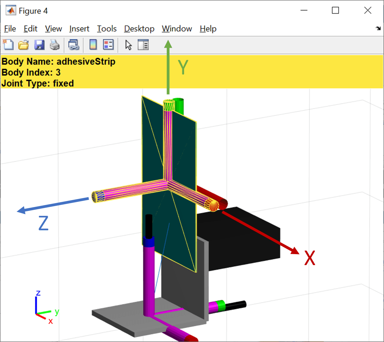
As indicated by the red, green, and blue tip highlighting on the violet reference joint marker, the Z axis is orthogonal to the part, while the Y axis points away from the L bracket that attaches to the gripper.
Therefore, the following rules must be satisfied regarding part orientation:
When picking up the part, the Z axis must point at the feeder, and the Y axis should be in-line with the global Y axis.
When applying glue, the Z axis must point at the dispenser.
When applying a part, the Z axis should be pointed at the part, with the Y axis pointed down, so that the L bracket is above the part.
Adjust Configuration to Avoid Collisions
Determine which bodies are in collision by selecting Check Collisions in the toolstrip. The red highlighting in the scene and the icons on the left show the objects in collision. Selecting an object shows the objects it is colliding with in the scene inspector.
From this view, see that the upper arm and gripper base links are in collision with the tool station base, and the adhesive strip is in collision with the part feeder.

From this view, it can be seen that the upper arm and gripper base links are in collision with the tool station base, and the adhesive strip is in collision with the part feeder. The latter is expected as the original marker pose target coincides with the same position as the part feeder. However, assuming the part will lay flat on the feeder, the end effector can be retracted such that the end effector has enough clearance to pick up the part.
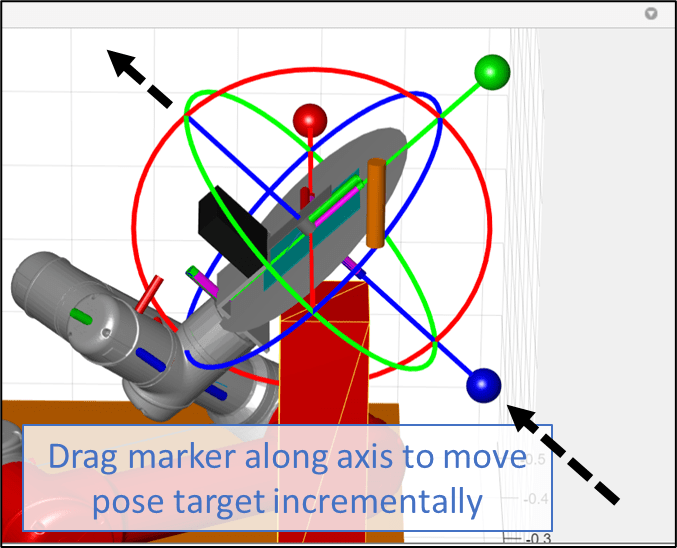
To make this change, click on the lateral Z axis grip of the marker, and drag the marker along its local Z axis.
Click Check Collision again to verify that the adhesive and gripper bodies are no longer in collision.
The second collision is between the tool station base and two links in the robot. To avoid these in-collision configurations, use constraints such as the Cartesian bounds constraint to adjust the solver so that it no longer finds configurations in which the forearm and upper arm can collide with the base.
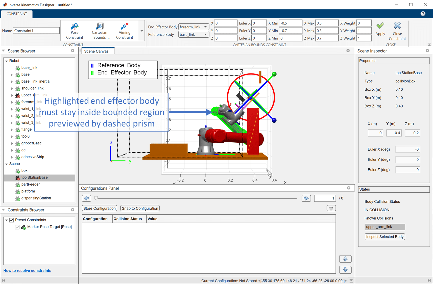
A bounds constraint can be used to keep bodies inside a particular bounded range. In this case, the aim would be to keep the distal end of the upper arm from contacting the base. Since that end of the link is near coincident with the original (and reference point) of the forearm link, a Cartesian Bounds constraint that prevents the forearm from reaching the base along Y should prevent this collision. To add this, click Add Constraint > Cartesian Bounds Constraint.
Create a target bounded region for the manipulator that avoids the tooling station base. Set the default upper Y bound to 0.3 meters and the default upper Z bound to 0.7 meters creates a region for this body to be in that avoids the base. Additionally, set the weight on the X direction to 0 since the range in that direction is unlimited. Observe the preview in the image below.
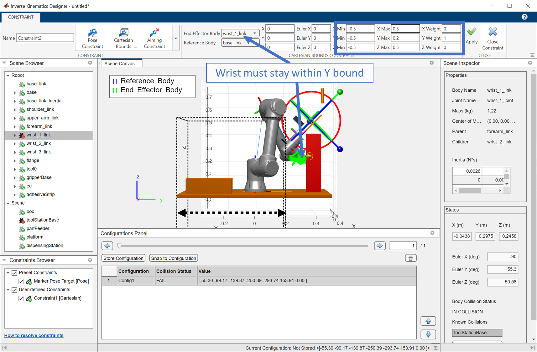
Click Apply to apply the constraint, then close the constraints browser. The robot is now repositioned and collision-check confirms that while the arm links are no longer in collision with the base, the wrist is still in collision. Create another Cartesian bounds constraint with a Y range of -0.5 meters to 0.2 meters to prevent this collision. Set the weights on the other bounds to 0, so that only Y is considered.
Apply the changes and exit the Constraints tab. Then click Check Collisions again verify that the configuration is collision-free.
While the solution is now collision-free and visually close to the target, the marker pose target constraint is not met. Click Refresh Solver to attempt to see if the solver can find another solution. Try this a few times. If the solver cannot find a solution where the marker pose target constraint is not met, modify the solver parameters so it can find a solution that satisfies all constraints during its execution time.
The default solver parameters are set to be fairly fast with just 50 iterations, which can struggle with a higher number of constraints. In the toolstrip, click Solver Settings or select the Solver tab. Then set the value of the number of Maximum Iterations to 500. Click Apply to run the solver and return to the Inverse Kinematics tab.

The robot should now be in a configuration that is collision-free and meets all constraints.
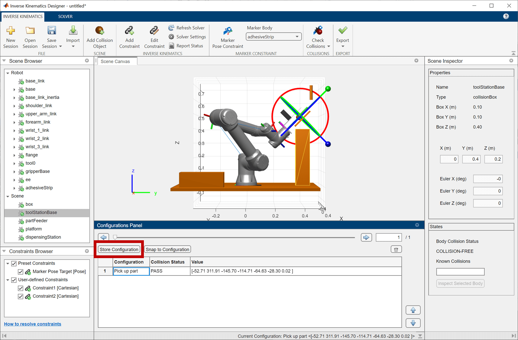
Once satisfied with the configuration, store it by clicking Store Configuration in the Configurations Panel. Rename the configuration to Pick up part.
The method used above to find a solution, i.e. adding constraints and extending solver run-time, is one way to ensure a result can be reached. Another method is to give the solver different starting configurations. Since each call to inverse kinematics uses the current configuration as the initial guess, you can "help" the solver by putting the robot in a pose that appears near satisfaction. This may be done by setting selecting links and modifying their joint values directly in the scene inspector, or by using the marker pose target to move the robot around. You can also continue to click Refresh Solver or modify the parameters further to search for different configurations if unsatisfied with the current one.
Apply Glue to Part at Dispensing Station
The next pose is below the dispensing station. For this constraint to be reachable, the second Cartesian constraint must be removed. De-select the constraint by clicking the check box next to Constraint2 [Cartesian]. Alternatively, right-click on it and delete it since it is no longer needed.
Next, click on the dispensing station to determine its global pose and dimensions, then modify the marker target pose so it lies at the base of the dispensing station. Since the dispensing station is located at [0.25 0.45 0.65] meters and has length 0.1 meters, set the target pose to 0.05 meters below the origin of the dispensing station at [0.25 0.45 0.6] meters. With the orientation set to [0 0 0] degrees so the Z axis of the adhesive strip is pointing at the dispensing station.
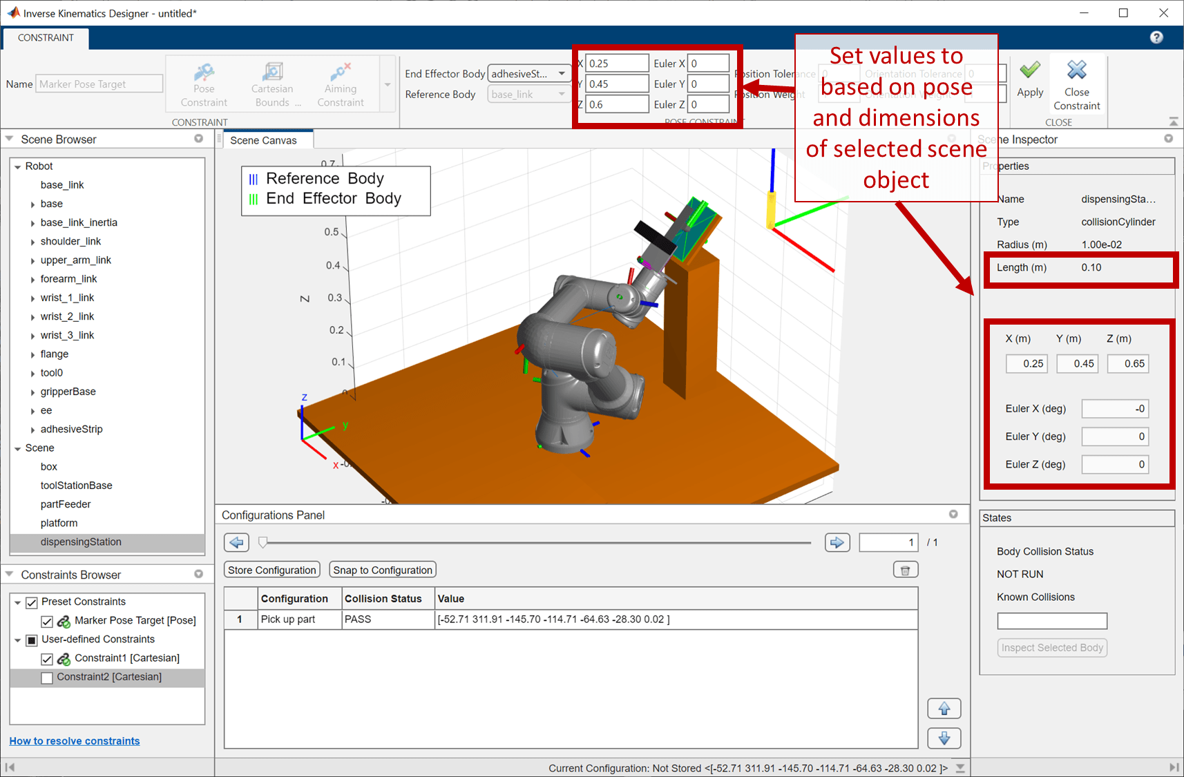
Apply the changes and exit the Constraints tab. Then drag the Z axis of the marker to provide some clearance between the part and the dispensing station. Check collisions and verify that the pose is collision-free.
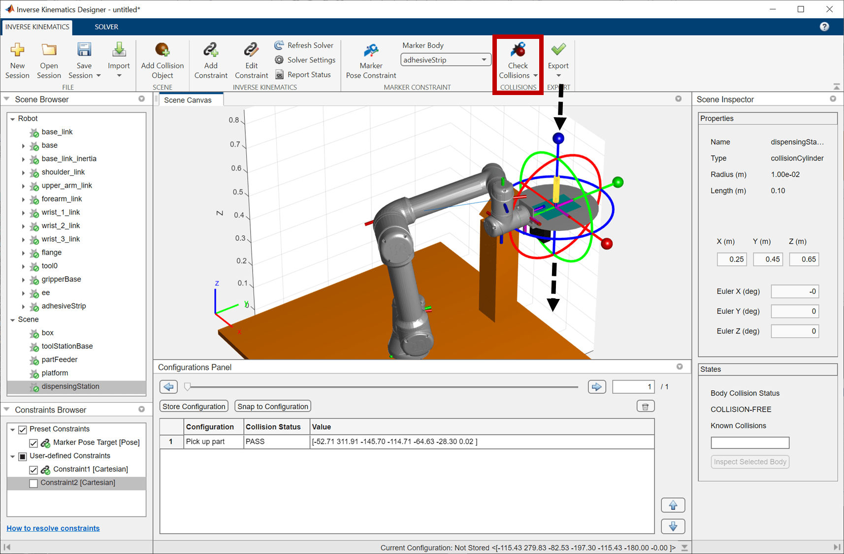
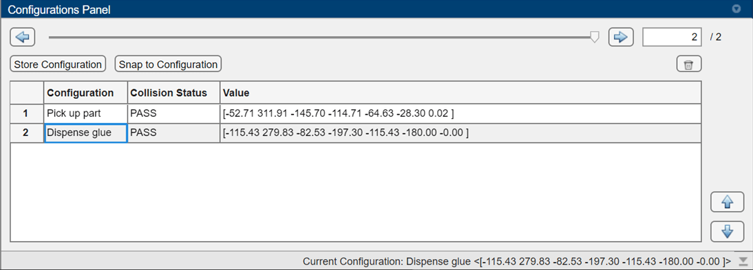
Lastly, store the configuration and rename it to Dispense glue.
Apply Strips to Product
For the final configuration, the part will be applied to the box. As with the previous two configurations, the pose will be based off of the part location.
Start by determining the target pose. Click on the box, and choose a target that will orient the gripper orthogonally to the box with the L bracket above the box. Based on the position of the box, [0.3 -0.3 -.05], the gripper should be placed in the center of the box pointing outward, but with clearance for the 0.15 meter long strip to be placed without colliding with the platform. An example of such a position is [0.2 -0.3 0] meters. Using the orientation rules described, the Z axis of the gripper must point towards the box, along the global X axis, and the Y axis of the gripper must point down, towards the platform.
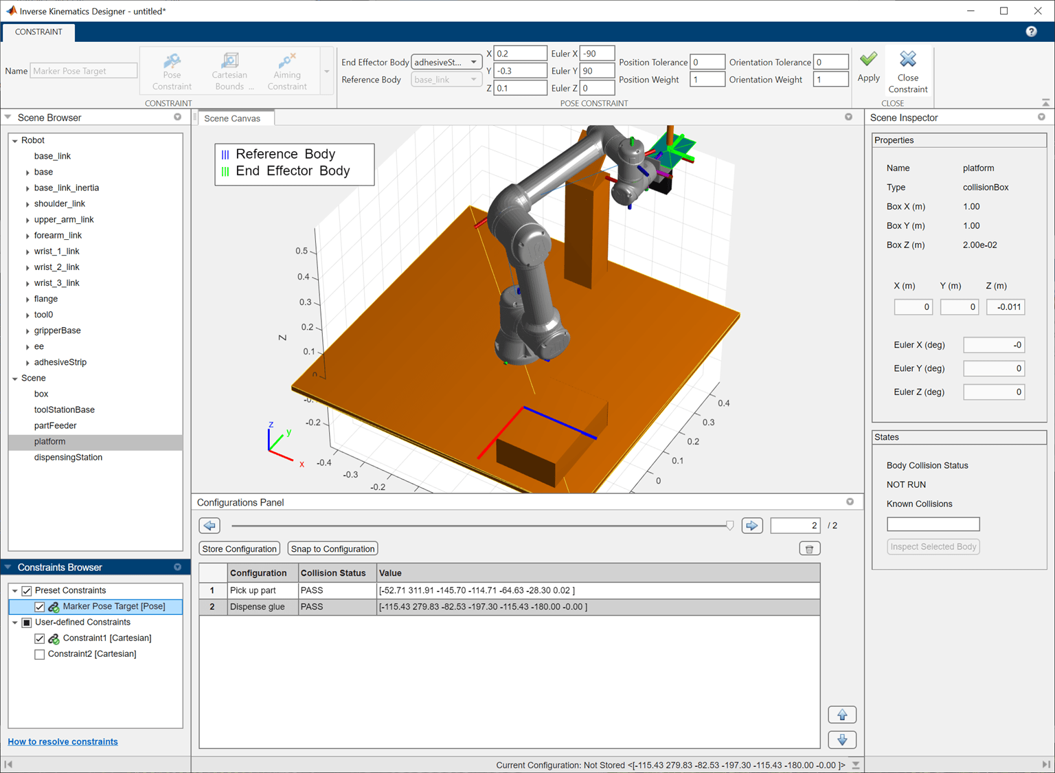
Apply the constraint, then exit the tab. Check collisions and observe that the robot has reached the configuration, but is still in collision with the box. Again, this is expected due to the positions coinciding. Provide a bit of clearance by dragging the Z axis of the marker to move the gripper. You can see the pose of the selected link in the Scene Inspector whenever the marker is released.
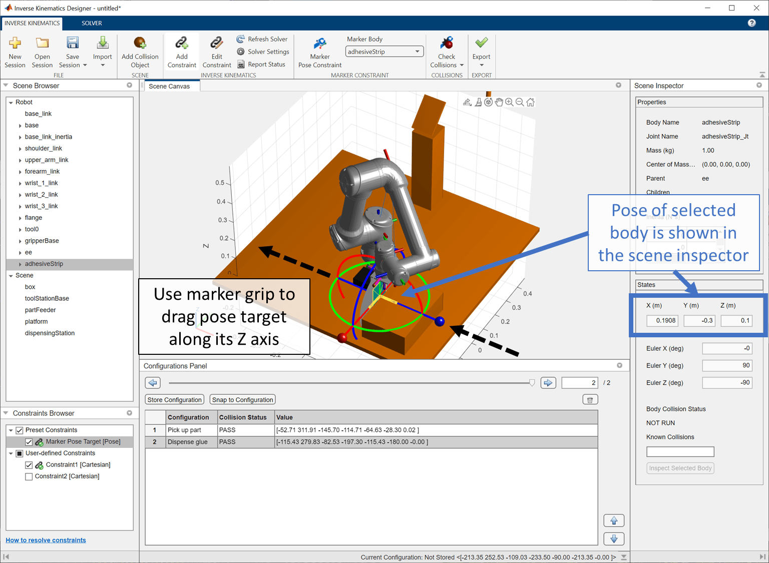
After verifying that the last configuration is collision-free, save it to the Configurations Browser.

Check that there are no collisions in any of the configurations and iterate through the waypoints.
Export Waypoints and Plan Path
Now that all waypoint configurations have been designed, click Export Path to export the waypoints to the workspace. Specify the name of the waypoint matrix, shift-click to select all waypoints, and click Export. The set of ordered waypoints now exist as a matrix of configurations in the workspace.
Plan Path Between Waypoints
Since the path between these waypoints is direct and clear of obstacles, a trapezoidal velocity profile trajectory could be used to connect these waypoints with smooth trajectories that stop at each waypoint.
However, because the robot is very close to the collision objects, it is more prudent to use a path planner. Use the manipulatorRRT function to plan a path between the three waypoints created in Inverse Kinematics Designer.
load pathWaypointData.mat
env = {dispensingStation partFeeder toolStationBase platform box};
planner = manipulatorRRT(ur5e_robot,env);
planner.MaxConnectionDistance = 0.45;
planner.ValidationDistance = 0.1;
planner.SkippedSelfCollisions = "parent";

rng(10);
numPts = 25;
numWaypoints = size(pathWaypoints,1);
paths = cell(1,numWaypoints);
for segIdx = 1:numWaypoints
    tic;
    plannedPath = plan(planner, pathWaypoints(segIdx,:), pathWaypoints(mod(segIdx,numWaypoints)+1,:));
    shortenedPath = shorten(planner, plannedPath, 10);
    paths{segIdx} = interpolate(planner, shortenedPath, 10);

    segTime = toc;
    disp(['Done planning for segment ',num2str(segIdx),' in ',num2str(segTime), ' seconds']) %i in %f seconds\n])
end
Done planning for segment 1 in 2.9326 seconds
Done planning for segment 2 in 8.305 seconds
Done planning for segment 3 in 4.8136 seconds
A complete path can be made by combining the segments.
totalSegs = vertcat(paths{:});Visualize Completed Trajectory
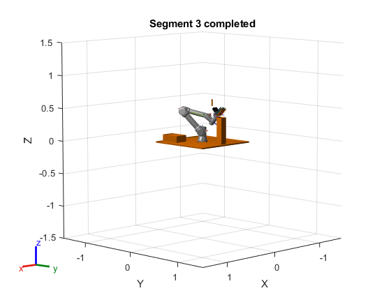
Now that the waypoints have been planned, play back the path to make sure it works.
ax = show(ur5e_robot);
hold all
for i = 1:numel(env)
    env{i}.show("Parent", ax);
end

% Display the figure window the animation
pathFig = ancestor(ax, 'figure');
set(pathFig, "Visible", "on")

% Set up timing and configure robot
r = rateControl(10);
tvec = linspace(1,numWaypoints,numWaypoints*numPts);
ur5e_robot.DataFormat = "row";

% Animate all path segments
for pathSegIdx = 1:numel(paths)
    path = paths{pathSegIdx};

    % For each path segment, step through all the configurations
    for configIdx = 1:size(path,1)
        show(ur5e_robot, path(configIdx,:), "FastUpdate",true, "PreservePlot",false,"Parent",ax);
        waitfor(r);
    end

    % Hold the pose and update the title each time a waypoint is reached
    title(sprintf('Segment %i completed', pathSegIdx), "Parent",ax);
    pause(1);
end
Next Steps
Once satisfied with the path, this workflow can be completed by smoothing the paths using trajectories and incorporating them into a higher-level workflow. For example, these paths may be deployed to a robot using hardware tools, integrating with hardware tools to actuate the gripper. See Get Started (Robotics System Toolbox Support Package for Kinova Gen3 Manipulators) for more information.
