Generate INS Sensor Measurements from Interactive Driving Scenario
The Driving Scenario Designer app enables you to create driving scenarios interactively and generate synthetic sensor data for testing your automated driving algorithms. In driving scenarios that represent geographic locations, you can add a sensor that fuses measurements from an inertial navigation system (INS) and global navigation satellite system (GNSS) such as a GPS, and generate the fused measurements. You can then export this synthetic inertial sensor data to MATLAB® for further analysis.
Import Road Network
To generate realistic INS and GNSS sensor data from the app, you must use a road network that is based on a real-world geographic location. This example uses a road network that is imported from OpenStreetMap®. It is the same road network used in the Import OpenStreetMap Data into Driving Scenario example.
Open the Driving Scenario Designer app.
drivingScenarioDesigner;
On the app toolstrip, select Import and then OpenStreetMap. Open the applehill.osm file in the example folder. The file was downloaded from https://www.openstreetmap.org, which provides access to crowd-sourced map data all over the world. The data is licensed under the Open Data Commons Open Database License (ODbL), https://opendatacommons.org/licenses/odbl/.
After you load the file, the Select Roads section of the dialog box displays the road network for the bat365® Apple Hill campus.
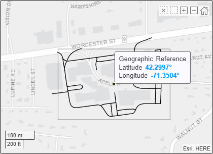
To keep the driving scenario simple for this example, click to select only the bottom-left road segment for import.
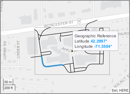
Click Import. The app imports the road and generates a road network.
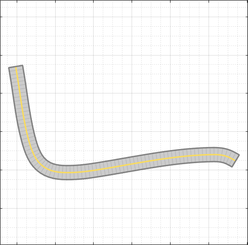
Add Actor and Trajectory
To create a trajectory that is compatible with INS and GNSS sensor readings, the trajectory must be smooth, with minimal jerk and no discontinuities in acceleration. Create an actor and specify a trajectory that follows the road.
On the app toolstrip, select Add Actor and then Car. On the Scenario Canvas, click to add the car to the right end of the road.
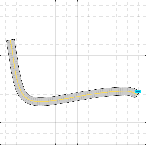
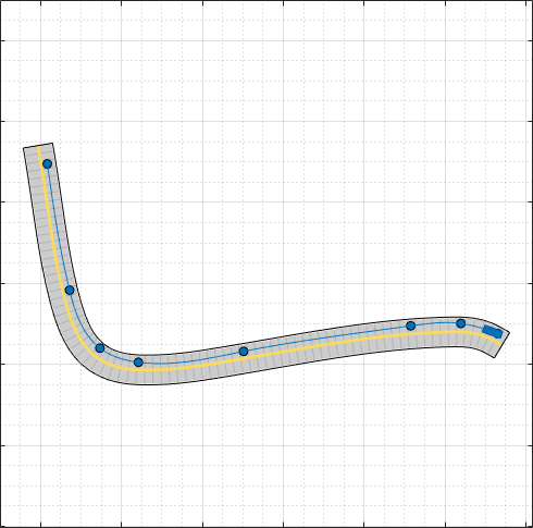
Right-click the car and select Add Forward Waypoints. Then, click to add waypoints along the length of the road. When you add the last waypoint, press Enter to commit the trajectory to the road.
Smooth the Trajectory
By using the default trajectory values, the car travels at a constant speed of 30 m/s (about 67 mph) through each waypoint. This speed is suitable for a highway scenario, but not for the geographic location used in this example. Reduce the speed of the car to 5 m/s (about 11 mph), and specify slower speeds around the turn.
On the Actors tab at the left, in the Trajectory section, set Constant Speed (m/s) to 5. In the Waypoints, Speeds, Wait Times, and Yaw table, the app reduces the v (m/s) values from 30 to 5.
For the waypoints around the turn, reduce the v (m/s) values to 4. In this sample trajectory, the car slows down to 4 m/s when it reaches waypoint 5, maintains this speed through waypoints 6 and 7, and speeds back up to 5 m/s by the time it reaches waypoint 8.
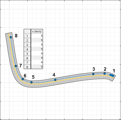
Select Use smooth, jerk-limited trajectory, which is a required parameter for working with INS sensor simulation.If you receive an error that the app is unable to create a smooth trajectory, try making the following changes:
Increase the distance between the waypoints where the car reduces speed (between waypoints 4 and 5 in the previous image). The extended distance gives the car more time to decelerate. Similarly, you can also extend the distance between the waypoints where the car increases speed (between waypoints 7 and 8 in the previous image).
Reduce the speed values, and check that the difference in speed between waypoints is not too great. Using the previous image as an example, if you had specified a speed of 10 m/s for the last waypoint, the car would not have enough space to accelerate to that speed from 4 m/s.
Increase the Jerk (m/s3) parameter value. Increasing this value increases the number of possible trajectories that the app can compute at the expense of reduced comfort for human passengers.
Add INS Sensor
Mount the INS sensor to the car.
On the app toolstrip, click Add INS. On the Sensor Canvas, click to add the INS sensor to the predefined Rear Window location. Placing a sensor at this location mounts the sensor at the ego vehicle origin.
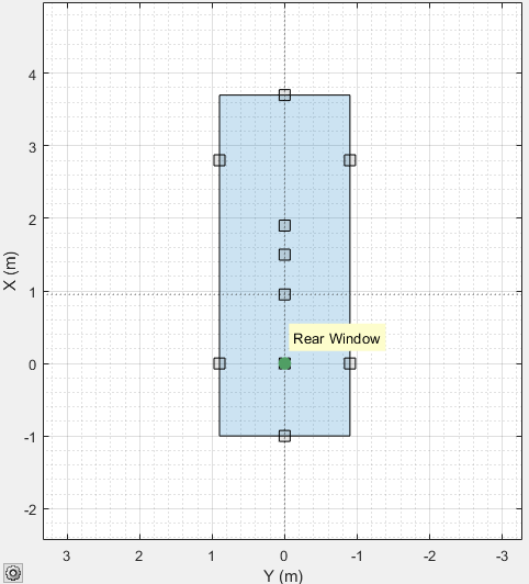
(Optional) On the Sensors tab at the left, modify the measurement parameters of the sensor. For example, you can modify the accuracy of the yaw, pitch, and roll readings, or the accuracy of position, velocity, and acceleration measurement.
Simulate Scenario
Generate INS data from the scenario by simulating the scenario. On the app toolstrip, click Run. The Bird's-Eye Plot shows no sensor data because the app does not support INS sensor visualization.
If the simulation runs too slowly given the slow speeds used in the trajectory, increase the sample time of the scenario. On the app toolstrip, click Settings, and adjust the Sample Time (ms) parameter.
Export to MATLAB and Explore Sensor Data
The Driving Scenario Designer app enables you to export data from the most recent simulation run. Export the scenario sensor data to the MATLAB workspace and view the generated INS measurements.
On the app toolstrip, select Export and then Export Sensor Data. Name the sensor data variable to be exported sensorData and click OK.
Explore the exported sensor data. The exported data is a structure array containing actor poses and sensor data at each simulation time step. Because the scenario contains no sensors that produce object detections, lane detections, or point clouds, the corresponding structure fields are empty arrays. The number of structures shown here differs from the number in your exported variable.
sensorData
View the data for the first INS measurement. INS measurements are stored in a cell array of structures. Because the scenario contains only one INS sensor, the cell array has only one structure. The fields of the INS measurement structure are the same as the fields produced when you generate measurements from an insSensor System object™. The INS measurement shown here will differ from the measurement in your exported variable.
sensorData(1).INSMeasurements{:}
Alternatively, by selecting Export and then MATLAB Function from the app, you can export a MATLAB function for reproducing the scenario and INS sensor at the MATLAB command line. The INS sensor returned by this function is an insSensor System object.
Export Scenario and Sensor to a Simulink Model
The Driving Scenario Designer app enables you to export the scenario and sensors to a Simulink® model. Save the scenario as INSTestScenario.MAT. To generate Simulink blocks for the scenario and its sensors, on the app toolstrip, select Export > Export Simulink Model. This model shows sample blocks that were exported from the app.

