Detection Concatenation
Combine detection reports from different sensors
Libraries:
Automated Driving Toolbox
Sensor Fusion and Tracking Toolbox /
Utilities
Description
The Detection Concatenation block combines detection reports from multiple sensors onto a single output bus. Concatenation is useful when detections from multiple sensor blocks are passed into a tracker block such as the Multi-Object Tracker block. You can accommodate additional sensors by changing the Number of input sensors to combine parameter to increase the number of input ports.
Examples
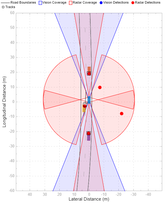
Sensor Fusion Using Synthetic Radar and Vision Data in Simulink
Implement a synthetic data simulation for tracking and sensor fusion in Simulink® with Automated Driving Toolbox™.
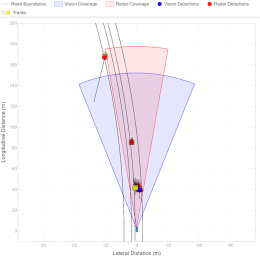
Adaptive Cruise Control with Sensor Fusion
Implement an automotive adaptive cruise controller using sensor fusion.
Ports
Input
In1, In2, ..., InN — Sensor detections to combine
Simulink buses containing MATLAB® structures
Sensor detections to combine, where each detection is a Simulink bus containing a MATLAB structure. See Create Nonvirtual Buses (Simulink) for more details.
The structure has the form:
| Field | Description | Type |
|---|---|---|
NumDetections | Number of detections | integer |
Detections | Object detections | Array of object detection structures. The first
NumDetections of these
detections are actual detections. |
The fields of Detections
are:
| Field | Description | Type |
|---|---|---|
Time | Measurement time | single or
double |
Measurement | Object measurements | single or
double |
MeasurementNoise | Measurement noise covariance matrix | single or
double |
SensorIndex | Unique ID of the sensor | single or
double |
ObjectClassID | Object classification ID | single or
double |
MeasurementParameters | Parameters used by initialization functions of tracking filters | Simulink Bus |
ObjectAttributes | Additional information passed to tracker | Simulink Bus |
By default, the block includes two ports for input detections. To add more ports, use the Number of input sensors to combine parameter.
Output
Out — Combined sensor detections
Simulink bus containing MATLAB structure
Combined sensor detections from all input buses, returned as a Simulink bus containing a MATLAB structure. See Create Nonvirtual Buses (Simulink).
The structure has the form:
| Field | Description | Type |
|---|---|---|
NumDetections | Number of detections | integer |
Detections | Object detections | Array of object detection structures. The first
NumDetections of these
detections are actual detections. |
The fields of Detections
are:
| Field | Description | Type |
|---|---|---|
Time | Measurement time | single or
double |
Measurement | Object measurements | single or
double |
MeasurementNoise | Measurement noise covariance matrix | single or
double |
SensorIndex | Unique ID of the sensor | single or
double |
ObjectClassID | Object classification ID | single or
double |
MeasurementParameters | Parameters used by initialization functions of tracking filters | Simulink Bus |
ObjectAttributes | Additional information passed to tracker | Simulink Bus |
The Maximum number of reported detections output
is the sum of the Maximum number of reported
detections of all input ports. The number of actual
detections is the sum of the number of actual detections in each input
port. The ObjectAttributes fields in the detection
structure are the union of the ObjectAttributes
fields in each input port.
Parameters
Number of input sensors to combine — Number of input sensor ports
2 (default) | positive integer
Number of input sensor ports, specified as a positive integer. Each input port is labeled In1, In2, …, InN, where N is the value set by this parameter.
Data Types: double
Source of output bus name — Source of output bus name
Auto (default) | Property
Source of output bus name, specified as Auto or
Property.
If you select
Auto, the block automatically generates a bus name.If you select
Property, specify the bus name using the Specify an output bus name parameter.
Specify an output bus name — Name of output bus
no default
Dependencies
To enable this parameter, set the Source of output bus
name parameter to Property.
Simulate using — Type of simulation to run
Interpreted execution (default) | Code generation
Interpreted execution— Simulate the model using the MATLAB interpreter. This option shortens startup time. InInterpreted executionmode, you can debug the source code of the block.Code generation— Simulate the model using generated C/C++ code. The first time you run a simulation, Simulink generates C/C++ code for the block. The C code is reused for subsequent simulations as long as the model does not change. This option requires additional startup time.
Extended Capabilities
C/C++ Code Generation
Generate C and C++ code using Simulink® Coder™.
Version History
Introduced in R2017bR2023a: Simulink buses do not show in workspace
As of R2023a, the Simulink buses created by this block no longer show in MATLAB workspace.
MATLAB Command
You clicked a link that corresponds to this MATLAB command:
Run the command by entering it in the MATLAB Command Window. Web browsers do not support MATLAB commands.

Select a Web Site
Choose a web site to get translated content where available and see local events and offers. Based on your location, we recommend that you select: .
You can also select a web site from the following list
How to Get Best Site Performance
Select the China site (in Chinese or English) for best site performance. Other bat365 country sites are not optimized for visits from your location.
Americas
- América Latina (Español)
- Canada (English)
- United States (English)
Europe
- Belgium (English)
- Denmark (English)
- Deutschland (Deutsch)
- España (Español)
- Finland (English)
- France (Français)
- Ireland (English)
- Italia (Italiano)
- Luxembourg (English)
- Netherlands (English)
- Norway (English)
- Österreich (Deutsch)
- Portugal (English)
- Sweden (English)
- Switzerland
- United Kingdom (English)
Asia Pacific
- Australia (English)
- India (English)
- New Zealand (English)
- 中国
- 日本Japanese (日本語)
- 한국Korean (한국어)

