How to Use Simulink for ISO 26262 Projects
By Tom Erkkinen, bat365
Automotive engineers working on safety-related, embedded systems for traditional and autonomous vehicles are looking for efficient ways to achieve the process rigor imposed by ISO® 26262 [1], a functional safety standard for road vehicle development.
With all the media attention paid to autonomous vehicles, there is no lack of advice. Too often, though, this advice focuses on the latest coding method or bug-zapping tool. As industry experts have long recognized, safety is more about getting the system and its requirements right than about the software and how it was coded [2].
With continuous- and discrete-time simulation as its backbone, Model-Based Design with Simulink® lets you design and test your full system under a wide range of driving conditions and fault scenarios long before you go to the proving grounds or perform fleet tests. It also supports process activities specified by ISO 26262, including tool qualification. IEC Certification Kit details this support and provides tool certificates and reports from the international certification authority TÜV SÜD.
This article presents the TÜV SÜD–approved workflow for using Simulink for ISO 26262 projects. It introduces ISO 26262 and Model-Based Design and then covers the following activities:
- Requirements development
- Design modeling
- Design verification
- Code generation
- Code verification
- Tool qualification
ISO 26262 and Model-Based Design
ISO 26262 includes guidance for manual design and code, as well as for Model-Based Design. In particular, it lists 5 different use cases of Model-Based Design [3]:
- Specification of software safety requirements
- Developing of the software architecture design
- Design and implementation of software units, with or without code generation
- Design, implementation and integration of software components, including code generation from software component models
- Static and/or dynamic verification
It also acknowledges some of the benefits of using Model-Based Design [3]:
Beside the specific reasons for using MBD (e.g. simulation or code generation), an adequately defined syntax and semantics is a basis for the achievement of criteria such as comprehensibility, unambiguity, correctness, consistency and verifiability of information or work products described by models especially when different parties are collaborating.
The standard mentions graphical modeling and notes that modeling tools employ semi-formal methods for software development. It states that modeling not only captures the functionality to be realized (the embedded software), but also enables simulation of the real physical system (vehicle model and environment model) to produce a full system model:
Models, together with the modelling and coding guidelines, can be used to design, implement and integrate software at a higher level of abstraction.
and,
Models can also serve as a means to enable or support verification activities (e.g. plant model needed for the hardware-in-the-loop testing of closed-loop controls by simulating the environment of the device under test). The use of models for verification purposes may enable the early and efficient detection of faults/failures in work products (including software), more efficient test case generation, highly automated testing, or even formal verification techniques
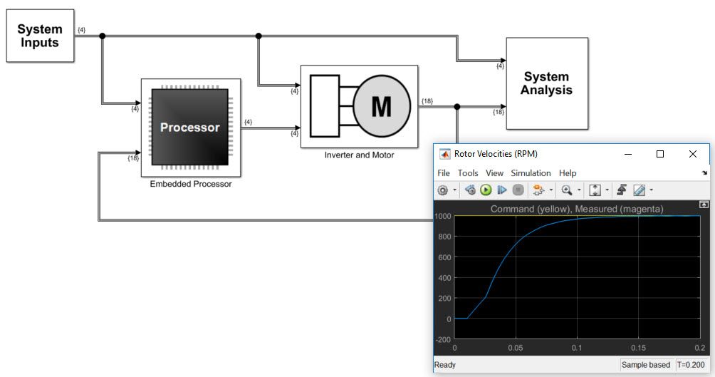
Figure 1 shows a typical Simulink closed-loop system model. It consists of a controller and plant, plus signal processors. In ISO 26262, the system requirements and architectural design specification constitutes an input to software development, but it is much more than that, as safety is fundamentally a systems issue [2].
Your system architectural elements allocated to software are typically elaborated until they become a software blueprint of sufficient detail for you to generate production code. ISO 26262 describes this model elaboration process as “model refinement” [2]:
Models themselves may consist of various hierarchical refinement levels or references to refined models at a lower hierarchical level (e.g. hierarchical structure with black box and white box views for each model element.)
ISO 26262 recommends methods for various activities based on Automotive Safety Integrity Levels (ASILs). You use this guidance to establish an appropriate workflow based on your use cases. Figure 2 gives an overview of the ISO 26262 process. Solid arrows show development activities, while dashed arrows indicate verification and validation activities.
Requirements Development
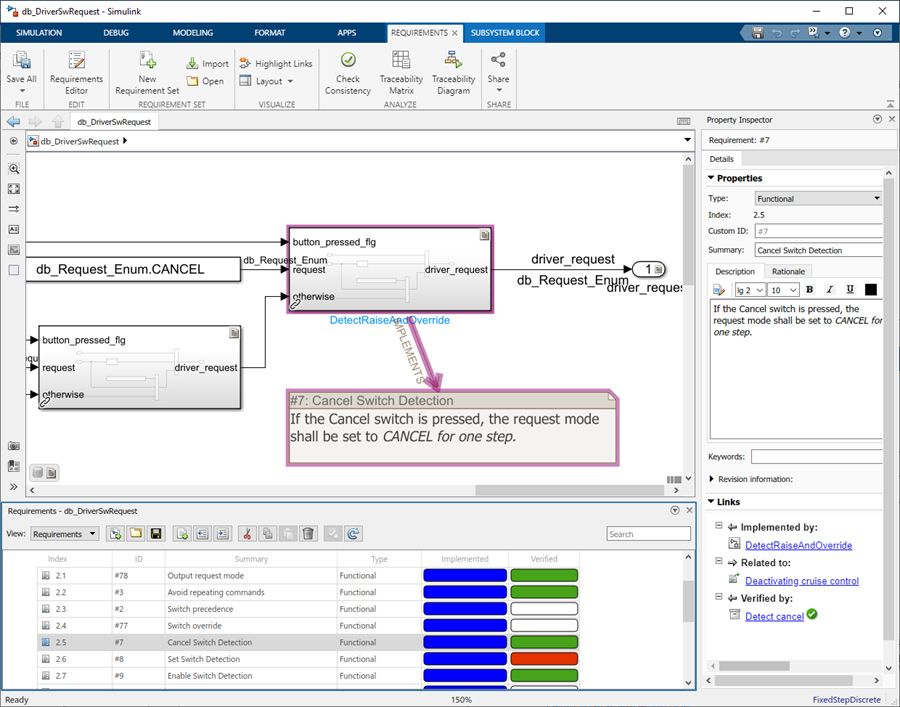
You start the safety-related development process by authoring functional and safety requirements. ISO 26262 recommends that you verify the software architecture design using “bi-directional traceability between the software architectural design and the software safety requirements.” To achieve this, you can use Requirements Toolbox™ to author and trace requirements to models, tests, and code. Requirements Toolbox supports bidirectional tracing for other tools, including Microsoft® Word®, Microsoft Excel®, and IBM® Rational® DOORS®. Further, you can use Simulink and Requirements Toolbox to create formal and unambiguous requirement specifications. The implementation and verification status of the requirements is monitored and managed within Requirements Toolbox. Requirement links can appear in the generated code (Figure 3).
Design Modeling
You can use Model-Based Design with Simulink and System Composer to specify your software architectural design. This includes the static (i.e., structure with block hierarchies and interface information) and dynamic aspects (i.e., behavior with functions, logic, data and control flow).
With Simulink, you can also refine functional models of your software units and components from high-level executable specification to a detailed design ready for production code generation. Typical refinements include:
- Converting blocks from continuous-time (S domain) to discrete-time (Z domain) using the Simulink Control Design™ discretization tool
- Converting data from double precision to single precision or fixed point using Fixed-Point Designer™
- Adding diagnostics, mode logic, state machines, and scheduling using Stateflow®
For ASIL A through D, ISO 26262 highly recommends using modeling guidelines, and for this, you can use MAB Style Guidelines [4] and the high-integrity guidelines for ISO 26262 provided in Simulink. Simulink Check™ automates checking for both guidelines. It can flag issues, such as the insertion of noncompliant blocks, during edit-time. You can also include your own guidelines and checks that can also be configured as edit-time checks.
Design Verification
ISO 26262 recommends a number of static and dynamic methods for verifying software designs and implementations, including unit- and integration-level activities. For Model-Based Design, it states that “depending on the software development process the test objects can be the code derived from this model or the model itself, or both”
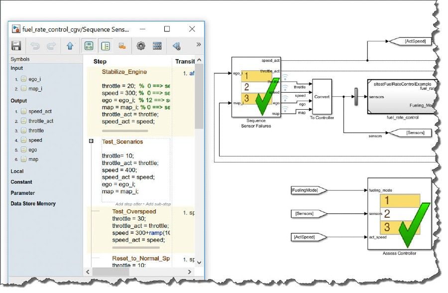
Simulink Test™ provides a framework for ISO 26262 verification and validation activities within Simulink. You can use it for authoring, managing, and executing systematic, simulation-based tests for models and for code generated from models. Figure 4 shows an example test sequence and assessment blocks.
The TÜV SÜD report in IEC Certification Kit (for ISO 26262) clarifies the role of Simulink Test in automating verification and validation:
[Simulink Test] allows the automation of core verification and validation activities for Simulink models and generated code. The following use cases reflect activities that are required in a software development process according to the Functional Safety Standards ISO 26262:
- Development and execution of tests for Simulink models
- Development and execution of tests for back-to-back testing between model and code
- Assessment of test results
- Generation of test reports
- Identification of traceability between requirements and tests cases
ISO 26262 recommends structural coverage analysis to determine test completeness and identify unintended functionality. It lists three methods for increasing rigor, with the last two being highly recommended for ASIL-D.
- Statement coverage
- Branch coverage
- MC/DC (Modified Condition/Decision Coverage)
The standard notes that for Model-Based Design, “the analysis of structural coverage can be performed at the model level using analogous structural coverage metrics for models.” It goes on to state that if the structural coverage is insufficient, “additional test cases shall be specified or a rationale shall be provided.”
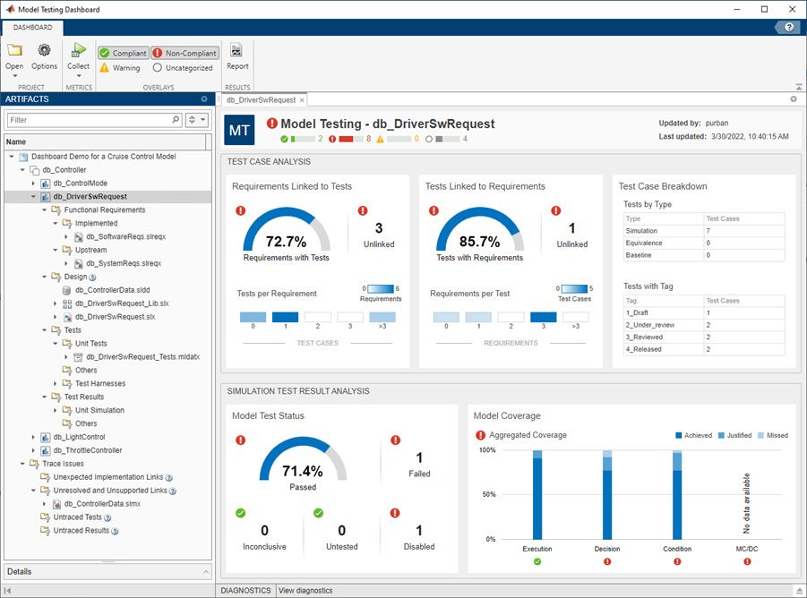
Simulink Coverage™ provides structural coverage analysis for models and generated code, and it is easily enabled for test execution with Simulink Test. If your model coverage is insufficient, you can use Simulink Design Verifier™ to automatically generate additional test cases to achieve the required coverage, including MC/DC. Simulink Check includes the Model Testing Dashboard for assessing requirements-based test cases and results for completeness and quality metrics in accordance with ISO 26262-6:2018, Clause 9.4.3 and Clause 9.4.5 (Figure 5).
IEC Certification Kit provides tool qualification support, with TÜV SÜD certificates and reports, for Simulink Check, Simulink Coverage (including model and code coverage), Simulink Design Verifier, and Simulink Test.
Code Generation
ISO 26262 states that “the implementation of the software units includes the generation of source code and the translation into object code.” To achieve this, you can use Embedded Coder® to generate C, C++, and AUTOSAR code from your Simulink and System Composer models. The code can comply with MISRA C®:2012 automatic code guidelines [5]. ISO 26262 notes that code guidelines for Model-Based Design and manual code can differ and lists MISRA® as an example.
IEC Certification Kit provides tool qualification support for Embedded Coder (including ASIL A through D) for C, C++, and AUTOSAR. Its TÜV SÜD certification report states:
Embedded Coder fulfills the requirements of ISO 26262 regarding tool support and automation.
The Embedded Coder is usually applied in one of the three following use cases:
- Generating C Code for the Model Used for Production Code Generation
- Generating C++ Code for the Model Used for Production Code Generation
- Generating C/C++ Code and Files for AUTOSAR Application Software Components from the Model Used for Production Code Generation
Embedded Coder provides options for optimizing code for memory and speed. In addition, you can generate processor-specific optimizations that leverage hardware accelerators such as SIMD® for ARM® and Intel®. You can verify that the optimized code matches the simulation results within prescribed tolerances, using model-to-code, processor-in-the-loop (PIL) testing as described in ISO 26262.
Executable object code is produced from the generated source code using your compiler and linker. The workflow in IEC Certification Kit allows coder, compiler, and processor optimizations, which are critical for mass production ECUs, as long as PIL testing is used to verify the executable object code.
Code Verification
ISO 26262 provides several options for verifying software designs and implementations. With Model-Based Design, you can compare model coverage to code coverage using Simulink Coverage during software-in-the-loop (SIL) testing, or you can use Simulink Code Inspector™.
Lastly, you can check MISRA compliance with Polyspace Bug Finder™. Use of MISRA checking and code coverage analysis is especially helpful if your project includes a mixture of generated and manually coded software. For added rigor, you can use Polyspace Code Prover™ to prove the absence of run-time errors such as divide-by-zero.
IEC Certification Kit provides tool qualification support, with TÜV SÜD certificates and reports, for Polyspace® products.
After compiling and generating the executable code, you can reuse model tests on the code executing on the target processor using PIL testing (Figure 6).
ISO 26262 highly recommends back-to-back testing for ASILs C and D. It notes the importance of testing in a representative target hardware environment and stresses the need to be aware of differences between the test and hardware environments:
Differences between the test environment and the target environment can arise in the source code or object code, for example, due to different bit widths of data words and address words of the processors.
But as every computer scientist should know [6], there are many sources for potential numeric differences across platforms, especially for floating-point data. Some begin as minor but accumulate and grow, especially in feedback control systems. Thus, ISO 26262 lists various in-the-loop methods for back-to-back testing:
Software unit testing can be executed in different environments, for example:
—model-in-the-loop tests;
—software-in-the-loop tests;
—processor-in-the-loop tests; and
—hardware-in-the-loop tests.
Simulink Test automates in-the-loop testing, including SIL and PIL with Embedded Coder and HIL with Simulink Real-Time™, and provides pass/fail reports with coverage metrics from Simulink Coverage.
Tool Qualification
ISO 26262-8 describes additional supporting processes, including change control, configuration management, and documentation. These processes are supported by Simulink Projects, Simulink model differencing and merge, and Simulink Report Generator™, respectively.
The standard also provides tool classification and qualification guidance. It requires users to qualify the tools for their specific projects. IEC Certification Kit effectively prequalifies tools by providing typical use cases, reference workflows, tool classification analysis, software tool documentation, tool qualification plans, and validation tests. If your project involves the supported use cases and follows the reference workflow, you can produce the required tool qualification artifacts by adapting the certification kit’s template documents and executing the validation tests in your development environment.
TÜV SÜD reviews and audits bat365® tool development and quality processes, as well as bug reporting capabilities and tool pre-qualification artifacts, and certifies the results at each product release. IEC Certification Kit includes these TÜV SÜD certificates and reports, which are predicated on the need to follow an appropriate verification and validation workflow. The kit provides reference workflows based on typical tool use cases, such as those highlighted in this article.
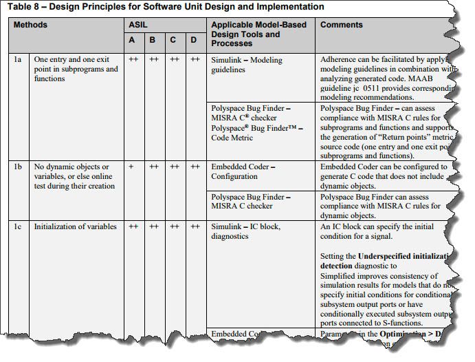
The kit provides more detailed information, including a mapping of ISO 26262 objectives to Simulink supporting capabilities (Figure 7).
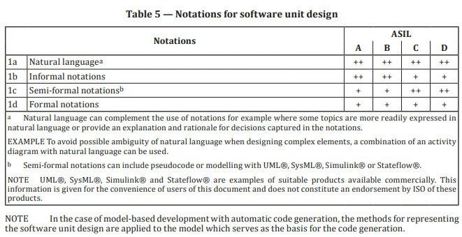
ISO 26262:2018 acknowledges that Simulink and Stateflow are suitable for Software Architecture and Software Unit Design Notation and as a basis for automatic code generation (Figure 8).
Note that the use of qualified tools does not ensure the safety of the software or system under consideration.
ISO 26262
ISO 26262 is an international functional safety standard for road vehicles [1]. It addresses possible hazards caused by malfunctioning, safety-related electronic/electrical (E/E) systems. It uses an Automotive Safety Integrity Level (ASIL) as a risk classification designation ranging from A to D, with ASIL D indicating the highest integrity level. The standard has nine normative parts, with guidelines in parts 10 and 11. Part 12 is an adaptation of parts 1-11 for motorcycles. Each part of the standard is provided as a separate document. ISO 26262 is goal-based and not prescriptive in nature, but it includes several hundred pages of guidance. Parts 4, 6, and 8 address systems [ISO 26262-4], software [ISO 26262-6], and tool qualification [ISO 26262-8], respectively.
Published 2022
References
-
ISO 26262:2018 Road vehicles — Functional safety
-
Nancy G. Leveson, Engineering a Safer World, Systems Thinking Applied to Safety
-
ISO 26262-6:2018 Road vehicles — Functional safety —Part 6: Product development at the software level
Products Used
Learn More
-
Kostal Receives ISO 26262 ASIL D Certification - user story
-
Model-Based Design for ISO 26262 – overview
-
High Integrity Modeling Guidelines - documentation
-
Embedded Coder for MISRA-C - overview
-
Applying Model-Based Design for ISO 26262 - Training
