YOLO v2 Vehicle Detector with Live Camera Input on Zynq-Based Hardware
This example extends the Deploy and Verify YOLO v2 Vehicle Detector on FPGA example by adding live HDMI video input and by targeting the postprocessing logic to the ARM® processor of the Xilinx® Zynq® UltraScale+(TM) MPSoC ZCU102 Evaluation Kit. The example uses the RGB for DL Processor reference design provided in the SoC Blockset™ Support Package for Xilinx® Devices.
The reference design passes the HDMI input to the preprocessing logic and also writes the input frame to processor memory (PS DDR). After preprocessing, the design writes the resized and normalized images to FPGA memory (PL DDR) where the data can be accessed by the deep learning (DL) processor. After the DL processor writes the output back to PL DDR, the postprocessing code on the ARM processor reads the output frames to calculate and overlay bounding boxes. The design returns these modified output frames on the HDMI output. You can also access the frames in Simulink® by using the Video Capture HDMI block.
This example follows the algorithm development workflow shown in the Developing Vision Algorithms for Zynq-Based Hardware (SoC Blockset) example.
The FPGA-targeted pixel-streaming design (DUT) in this example selects the region of interest (ROI) from the input frames to meet the requirements of the DL processor. The model selects a 1000-by-500 pixel region of the incoming 1920-by-1080 pixel video. Since the DL IP core cannot keep up with the incoming frame rate from the camera, the design also includes frame drop logic. The system processes frames only when the DL processor IP core is ready to accept data.
Set Up Environment
Before running this example, you must run the guided hardware setup included in the support package installation.
On the MATLAB Home tab Toolstrip, in the Environment section, click Add-Ons > Manage Add-Ons.
Locate SoC Blockset Support Package for Xilinx Devices, and click Setup.
The setup tool configures the target board and host machine, confirms that the target starts correctly, and verifies host-target communication.
For more information, see Set Up Xilinx Devices (SoC Blockset).
Download Video and Network Files
This example uses PandasetCameraData.mp4, that contains video from the Pandaset data set, as the input video and yolov2VehicleDetector32Layer.mat as the DL network. These files are approximately 47 MB and 2 MB in size. Download the .zip file from bat365 support website and unzip the downloaded file.
    PandasetZipFile = matlab.internal.examples.downloadSupportFile('visionhdl','PandasetCameraData.zip');
    [outputFolder,~,~] = fileparts(PandasetZipFile);
    unzip(PandasetZipFile,outputFolder);
    pandasetVideoFile = fullfile(outputFolder,'PandasetCameraData');
    addpath(pandasetVideoFile);
Configure Deep Learning Processor and Generate IP Core
The DL processor IP core accesses the preprocessed input from the PL DDR memory, performs vehicle detection, and loads the output back into the memory. To generate a DL processor IP core that has the required interfaces, create a deep learning processor configuration by using the dlhdl.ProcessorConfig (Deep Learning HDL Toolbox)InputRunTimeControl and OutputRunTimeControl parameters to indicate the type of interface between the input and output of the DL processor. To learn about these parameters, see Interface with the Deep Learning Processor IP Core (Deep Learning HDL Toolbox). In this example, the DL processor uses the register mode for input and output run-time control.
hPC = dlhdl.ProcessorConfig;
hPC.InputRunTimeControl = "register";
hPC.OutputRunTimeControl = "register";
Set the TargetPlatform property of the processor configuration object to Generic Deep Learning Processor. This option generates a custom generic DL processor IP core.
hPC.TargetPlatform = 'Generic Deep Learning Processor';
Use the setModuleProperty method to set the properties of the conv module of the DL processor. You can tune these properties to fit your design to the FPGA. To learn more about these parameters, see setModuleProperty (Deep Learning HDL Toolbox)LRNBlockGeneration on, turn SegmentationBlockGeneration off, and set ConvThreadNumber to 9.
hPC.setModuleProperty('conv','LRNBlockGeneration','on');
hPC.setModuleProperty('conv','SegmentationBlockGeneration','off');
hPC.setModuleProperty('conv','ConvThreadNumber',9);
To generate the quantized DL IP core, set the processor datatype to int8 (default datatype is single). To use the quantized workflow, you must have the Deep Learning Toolbox Model Quantization Library add-on installed.
hPC.ProcessorDataType = 'int8';
hPC.UseVendorLibrary = 'off';
This example uses the Xilinx ZCU102 board to deploy the DL processor. Use the hdlsetuptoolpath function to add the Xilinx Vivado synthesis tool path to the system path.
hdlsetuptoolpath('ToolName','Xilinx Vivado','ToolPath','C:\Xilinx\Vivado\2023.1\bin\vivado.bat');
To generate the DL IP core, call the dlhdl.buildProcessor function with the hPC object. It takes some time to generate the IP core.
dlhdl.buildProcessor(hPC);
The generated DL IP core contains a standard set of registers and the generated IP core report. The function also generates the IP core report, testbench_ip_core_report.html, in the same folder as the DL IP core.

IP core name and IP core folder are required in a subsequent step in Set Target Reference Design task of the IP core generation workflow for the rest of the FPGA-targeted design. The IP core report also has the address map of the input and output handshaking registers of the DL processor.

The registers InputValid, InputAddr, and InputSize contain the values of the corresponding handshaking signals that are required to write the preprocessed frame into DDR memory. The preprocessing logic pulses the inputNext register after it writes input data to memory. The helperSLYOLOv2Setup.m script sets up these register addresses. The other registers in the report are read and written from MATLAB®. For more details on interface signals, see the Design Processing Mode Interface Signals section of Interface with the Deep Learning Processor IP Core (Deep Learning HDL Toolbox).
Generate Bitstream and Deploy to FPGA
For simulating the DL processor, run the model from the Integrate YOLO v2 Vehicle Detector System on SoC. That model uses a reduced input image size, so the simulation is faster.
To start the targeting workflow with the model in this example, right click the YOLOv2 Preprocessing subsystem and select HDL Code > HDL Workflow Advisor.
 open_system('vzYOLOv2DetectorOnLiveCamera');
 close_system('vzYOLOv2DetectorOnLiveCamera/Video Viewer');
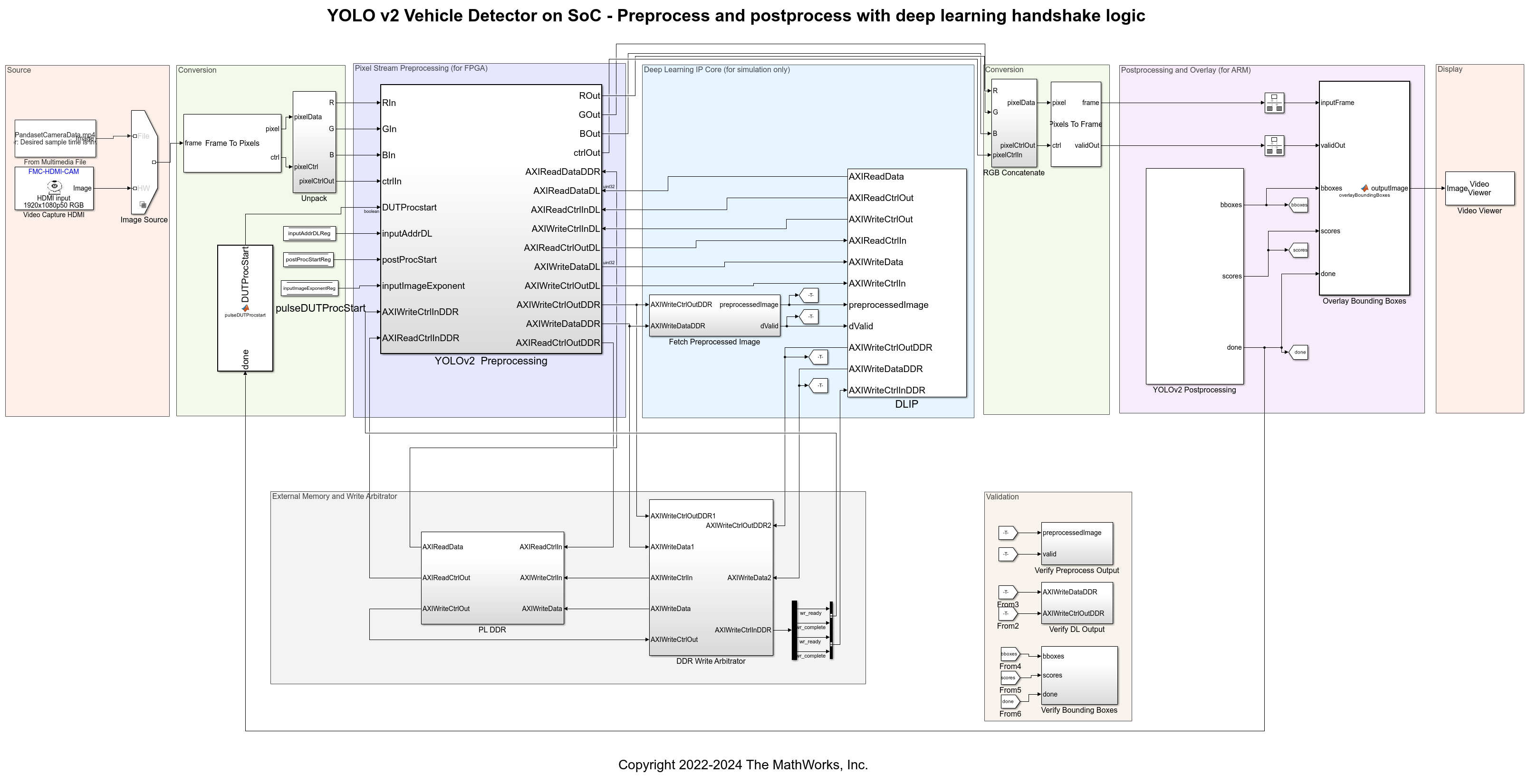
Configure the network for the vehicle detector using the helperSLYOLOv2DeploySetup function in the InitFcn callback of the model.
Refer to the following steps to find the InitFcn callback for the model.
In the Simulink Toolstrip, on the Modeling tab, in the Design gallery, click Property Inspector.
With no selection at the top level of your model or referenced model, on the Properties tab, in the Callbacks section, select the InitFcn.
In the box, enter the functions that you want callback to perform.
helperSLYOLOv2DeploySetup();
To deploy an 8-bit quantized network, set the networkDataType to 8bitScaled. To use the quantized workflow, you must have the Deep Learning Toolbox Model Quantization Library add-on installed.
helperSLYOLOv2DeploySetup('32Layer', '8bitScaled');
The script supports 2 networks, a 32 layer network(default) and a 60 layer network. To deploy the 60 layer network, set the networkConfig to '60Layer'.
helperSLYOLOv2DeploySetup('60Layer');
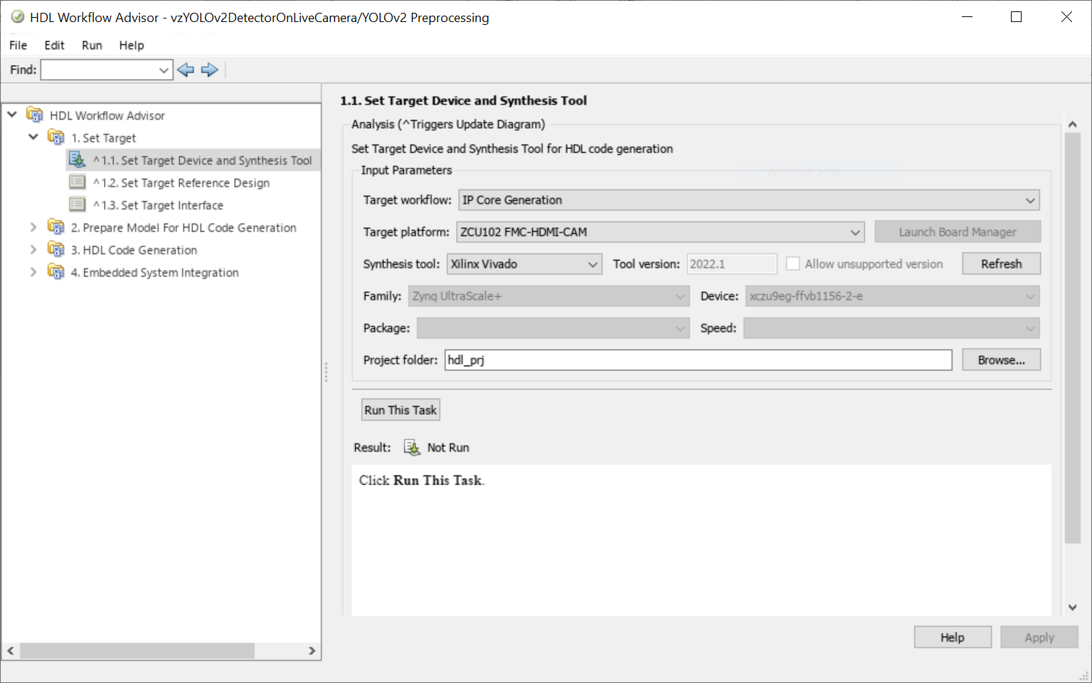
In step 1.1 of the HDL Workflow Advisor, set Target workflow to IP Core Generation and Target platform to ZCU102 with FMC-HDMI-CAM.
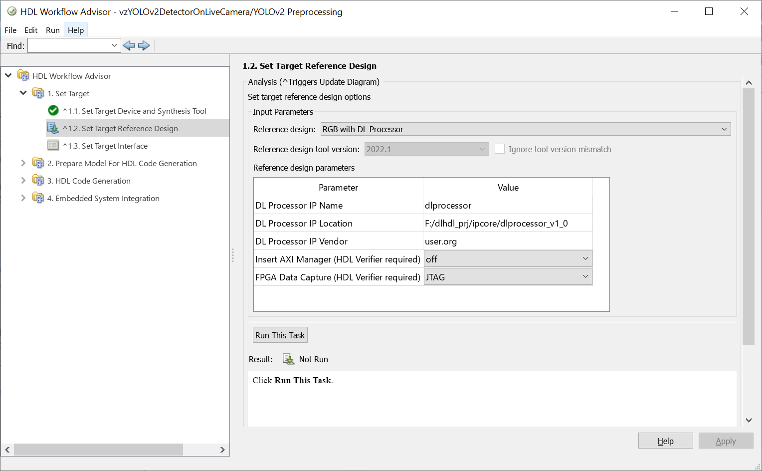
In step 1.2, set Reference design to RGB with DL Processor. Specify the name and location of the generated DL processor IP core from the IP core report. Specify the vendor name from the component.xml file of the DL processor IP core.
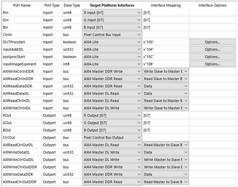
In step 1.3, map the input and output signals of the FPGA logic (in the left-most column) to the physical interfaces of the target (in the Target Platform Interfaces column).
Map the input and output R, G, and B streams to the R, G, and B ports in the target column. Similarly, map the
CtrlInandCtrlOutsignals to the respectivePixel Control Bussignals in the target column.Map the
DUTProcstartregister to anAXI4-Literegister. Choosing the AXI4-Lite interface directs HDL Coder™ tools to generate a memory-mapped register in the FPGA fabric. You can access this register from software running on the ARM processor. When the ARM processor writes this register, it triggers the DL processor input handshaking logic.Map the
inputImageExponentregister to anAXI4-Literegister. ThevzYOLOv2PostProcessmodel sets theinputImageExponentregister to the given quantized network's exponent value.Map the
AXIWriteCtrlInDDR,AXIReadCtrlInDDR,AXIReadDataDDR,AXIWriteCtrlOutDDR,AXIWriteDataDDR, andAXIReadCtrlOutDDRports to the matchingAXI4 Master DDRinterfaces. This interface implements the data transfer between the preprocess logic and the PL DDR. The preprocess logic writes the preprocessed data to the PL DDR, so the data can be read by the DL processor.Map the
AXIReadDataDL,AXIReadCtrlInDL,AXIWriteCtrlInDL,AXIReadCtrlOutDL,AXIWriteDataDL, andAXIWriteCtrlOutDLports to the matchingAXI4 Master DLinterfaces. This interface implements the handshaking logic between preprocess logic and the DL processor.
Step 2 of HDL Workflow Advisor prepares the design for generation by doing some design checks.
Step 3 generates HDL code for the IP core.
Step 4.1 integrates the newly generated IP core into the reference design.
In step 4.2, the advisor generates a targeted hardware interface model and, if the Embedded Coder Zynq support package has been installed, a Zynq software interface model. This example provides the vzYOLOv2PostProcess.slx model that contains the interface to the ARM processor, so you can uncheck Generate Simulink software interface model and Generate host interface script.
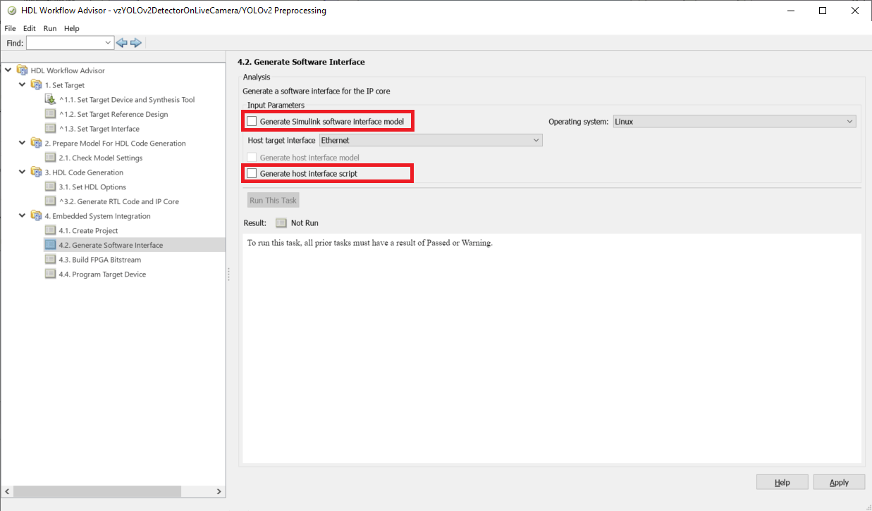
Click the Run this task button. The tool generates a bitstream for the FPGA, downloads it to the target, and restarts the board.
To manually configure the Zynq device with this bitstream file without running through the HDL Workflow Advisor again, copy the device tree file to the current working directory, then call downloadImage to program the FPGA.
copyfile(fullfile(matlabshared.supportpkg.getSupportPackageRoot, ...
  "toolbox","soc","supportpackages","zynq_vision","bin", ...
  "target","sdcard","visionzynq-zcu102-hdmicam","visionzynq-refdes", ...
  "visionzynq-zcu102-hdmicam-dl.dtb"),"visionzynq-zcu102-hdmicam-dl.dtb");
vz = visionzynq();
downloadImage(vz,'FPGAImage', ...
 '<PROJECT_FOLDER>\vivado_ip_prj\vivado_prj.runs\impl_1\design_1_wrapper.bit', ...
 'DTBImage', 'visionzynq-zcu102-hdmicam-dl.dtb')
Compile and Deploy Deep Learning Application
After you load the bitstream to the FPGA, follow these steps to deploy the end-to-end DL application.
Copy the dlhdl_prj\dlprocessor.mat file generated during IP core generation to the working folder. Call the updateBitstreamBuildInfo.m function to add the board and vendor information and generate a new .mat file to match the generated bitstream.
bitstreamName = 'design_1_wrapper';
updateBitstreamBuildInfo('dlprocessor.mat',[bitstreamName,'.mat']);
Create a target object to connect your target device to the host computer.
hTarget = dlhdl.Target('Xilinx','Interface','Ethernet','IpAddr','192.168.4.2');
Make sure that the generated .bit file with the same name as the generated bitstream is available in the working folder. Then, create a deep learning HDL workflow object. The dlNetwork variable is defined in helperSLYOLOv2DeploySetup. Run the helperSLYOLOv2DeploySetup function if the variable does not already exist in your workspace.
hW = dlhdl.Workflow('Network',dlNetwork,'Bitstream',[bitstreamName,'.bit'],'Target',hTarget);
Compile the network using the dlhdl.Workflow object.
frameBufferCount = 2;
compile(hW,'InputFrameNumberLimit',frameBufferCount);
Run the deploy function of the dlhdl.Workflow object to download the network weights and biases onto the Zynq UltraScale+ MPSoC ZCU102 board.
deploy(hW, 'ProgramBitStream', false);
Clear the workflow and hardware target objects.
clear hW;
clear hTarget;
Postprocess Video
You can run the vzYOLOv2PostProcess model in external mode on the ARM processor, or you can use it to fully deploy a software design. Either use of this model requires Embedded Coder™ and the Embedded Coder Support Package for Xilinx Zynq Platform.
Before running the model, you must configure the Xilinx cross-compiling tools. For more information, see Setup for ARM Targeting with IP Core Generation Workflow (SoC Blockset). In the postprocessing model, the YOLOv2PostprocessDUT subsystem is the same as the subsystem in the Integrate YOLO v2 Vehicle Detector System on SoC example. The postprocessing model configures the DL processor for streaming mode up to a specified number of frames. The AXI4 Stream IIO Read block reads the output data written to the PL DDR by the DL processor.
The YOLOv2PostprocessDUT subsystem calculates the bounding boxes and scores and sets the valid signal high. This valid signal synchronizes the input frames with the calculated bounding boxes and scores. The drawRect and setROI blocks use the valid signal to overlay the boxes and scores onto the output frames. AXI4-Lite registers transfer the control signals between the FPGA and the ARM.
Open the model and click on Build, Deploy and Start. This mode runs the algorithm on the ARM processor on the Zynq board.
open_system('vzYOLOv2PostProcess');
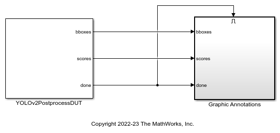
The vzYOLOv2PostProcess is configured with parameters DLOutputExponent, networkOutputSize to convert the DL output data to single or int8. The DLOutputExponent depends on the network used and set by the helperSLYOLOv2PostProcessSetup function.
Configure the vzYOLOv2PostProcess model using the helperSLYOLOv2PostProcessSetup function.
helperSLYOLOv2PostProcessSetup();
To run an 8-bit quantized network, set the networkDataType to 8bitScaled. To use the quantized workflow, you must have the Deep Learning Toolbox Model Quantization Library add-on installed.
helperSLYOLOv2PostProcessSetup('32Layer', '8bitScaled');
The vzYOLOv2PostProcess model contains only the postprocessing logic and does not include a Video Capture HDMI block. This model is intended to run on the board independently from Simulink and does not return any data from the board. To view the output video in Simulink, you can run a different model that contains a Video Capture HDMI block, such as the vzGettingStarted model. This model runs in Simulink while your deep learning design is deployed and running on the board. In the Video Capture HDMI block in the|vzGettingStarted| model, set Video source to HDMI input, Frame size to 1080p HDTV (1920x1080p), Pixel Format to RGB, and Capture Point to Output from FPGA user logic (B). In the To Video Display block, set Input Color Format to RGB and run the model. The bounding boxes and scores from the ARM processor display as overlays on the corresponding frame in the 'To Video Display' block.
To stop the executable on the ARM processor, run this command:
vz.stopExecutable('/tmp/vzYOLOv2PostProcess.elf');
Related Examples
More About
- Deep Learning Processing of Live Video (SoC Blockset)
