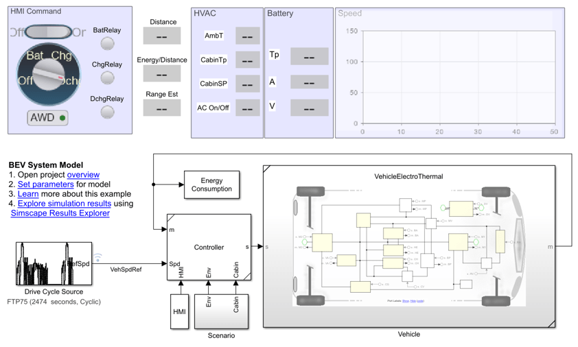
Detailed Battery Electric Vehicle (BEV) Model
This example shows how to design a battery electric vehicle (BEV) using high-fidelity models of vehicle components. You can use this model to perform detailed analysis at the component level. You can download this model in MATLAB® or access it from MATLAB Central File Exchange and GitHub®.
Example Overview
In this example, you learn how to:
Simulate an all-wheel-drive (AWD) or front-wheel-drive (FWD) vehicle.
Estimate the on-road range of the vehicle.
Size your high-voltage (HV) battery pack to achieve your desired range.
Setup your electric motor test bench for system integration.
Find the fixed gear ratio suitable for BEV application.
Generate a loss map for the motor and inverter.
Estimate the junction temperature variation of the semiconductor device, in the inverter power module, due to switching and predict the lifetime of the inverter.
Build a neural network model to predict battery temperature.

For more information about this example, follow these steps to explore the overview that opens in your web browser or see Electric Vehicle Design with Simscape (MATLAB Central File Exchange).
Download Files
Clone the up-to-date repository in the current folder using the gitclone function.
gitclone("https://github.com/simscape/Electric-Vehicle-Simscape");Alternatively, you can download the latest files using these options.
Download ZIP files of this project from Electric Vehicle Design with Simscape (MATLAB Central File Exchange).
Clone the Git™ repository from Electric Vehicle Design with Simscape (GitHub).
Open Project
After you use the gitclone function, MATLAB creates a new folder in the current folder. This example uses projects to manage the supporting files. Open the ElectricVehicleSimscape project file. If you have any projects open, MATLAB closes them before loading this project. An overview opens in your web browser that helps you explore subsystems and the construction of the model. The overview also shows you the main simulation results.
openProject("Electric-Vehicle-Simscape");Explore Project
To learn how to simulate an FWD or AWD powertrain, in the Documentation section of the overview, click the Battery Electric Vehicle Model link. The model represents an electric vehicle platform with two electric motors, the main drive in the front and one in the rear for the boost and all wheel drive modes. The coolant circuit maintains the temperature of the electric motors and battery within an operable range. An electric heater, in the coolant circuit, increases the battery temperature during startup in low temperature conditions. To estimate the load on the battery due to cooling and heating operations, the model includes heating, ventilation, and air conditioning (HVAC), and auxiliary loads.

To learn how to estimate the on-road range of the vehicle, in the Design Workflows section of the overview, click the Range Estimation for Battery Electric Vehicles link. This workflow shows you how to run drive cycles with different ambient conditions to determine the range of the vehicle with a given capacity. This plot shows the energy consumption and range of the BEV model when tested under the new European driving cycle (NEDC). LoTp indicates a low ambient temperature of -5 degC and HiTp indicates a high ambient temperature of 35 degC. AC indicates the HVAC is on and No AC indicates the HVAC is off. The highest total energy consumption and smallest range occur with the HVAC on, at low temperatures, because the HVAC heating load and battery heating put a heavy demand on the battery.

To learn how to setup a thermal durability test for the drive unit of a BEV, in the Design Workflows section of the overview, click the PMSM Thermal Test Bench for Battery Electric Vehicle (BEV) link. This figure shows the winding temperature at different gear ratios when tested under the extra urban driving cycle (EUDC). The drive unit reaches a failure point if the winding temperature reaches the insulation failure temperature. To determine an appropriate fixed gear ratio, you can run a design of experiment (DoE) which covers a range of gear ratios and test cycle parameters.

The PMSM Drive Unit Thermal Test Bench for Battery Electric Vehicle (BEV) example also shows how to estimate the lifetime of an inverter in terms of the number of vehicle cycles. You can estimate the number of vehicle cycles by converting the thermal cycling the converter experiences during a real life vehicle run into an equivalent number of test cycles. The drive unit reaches a failure point if the junction temperature of the insulated-gate bipolar transistor (IGBT) reaches the derating temperature. This figure shows the IGBT junction temperature for a real life duty cycle and a test cycle. Red circles indicate peaks and yellow stars indicate valleys.


To learn how to predict battery temperatures using a neural network model, in the Design Workflows section of the overview, click the Battery Neural Network Model for Temperature Prediction link. The predicted temperatures are close to the actual values.

To find the latest examples from the bat365 Simscape Team, see bat365 Simscape Team on MATLAB Central.
