Examine the Response of a Focused Phased Array
Introduction
This example introduces the concept of a focused beam, and shows how to use phased.FocusedSteeringVector to generate the required element weights for a phased array. It also shows how to use phased.SphericalWavefrontArrayResponse to compute the array response of an array at a given angle and range. First you will look at the response when a single beam is formed and examine characteristics of the focal region, then emulate a collection strategy commonly used in ultrasound imaging to see how a focused beam appears in an image.
Focused Beamforming
Spherical Wavefront Delay-and-Sum
Beamforming under the typical far-field assumption enables modeling the signal wavefront as a plane which is propagating along its normal direction. When the signal is incident on an array, the wavefront intersects individual elements with a relative time delay that is proportional to the distance of the element along the wave's propagation direction. Under this model, a delay (or phase shift, in the narrowband case) can be applied to each element such that the outputs across elements (whether on transmit or receive) have constructive phase when coherently summed.
Without the far-field assumption, the wavefront emanating from a point source is modeled as a spherical surface centered at that soure. This wavefront intersects the elements of the phased array with relative time delay dictated by the hyperbolic range across colinear elements. While this model would simply add unneccessary computation cost to the generation of a far-field pattern, the spherical wavefront model is necessary to understand near-field beamforming and focusing.
The function helperPlotULAWavefronts is provided to demonstrate the difference in element delays and wavefront shape between a steered beam with and without focusing. Element delays are relative to the array center.
figure
helperPlotULAWavefronts(14,1e6,1540,20,inf)
title('Steered Wavefront')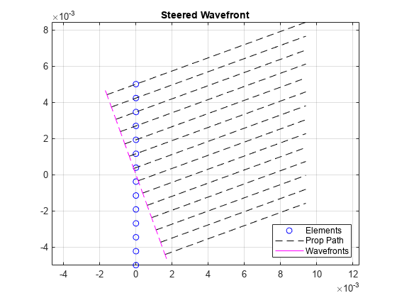
figure
helperPlotULAWavefronts(14,1e6,1540,20,0.01)
title('Steered and Focused Wavefront')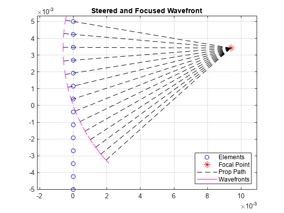
The Focal Region and Near/Far Boundary
In the far field, a steered array has a well-defined pattern in angle space, which is not dependent on range. In the near field, a steered (but unfocused) array has no discernabe lobe structure at all. Thanks to the nonlinear phase relationship between elements, a response that has equal magnitude at all ranges in a given direction is not possible. Instead, by focusing a beam one can obtain a small region, bounded in both angle and range, in which the response resembles a far-field response, known as the focal region. The angular position of the focal region may be controlled as easily as with a far-field beam. The position of the focal region in range is determined by the focal range, and the depth of field (DoF), which is the range extent of the region.
The figures below shows the progression of beam shape with range for focused uniform and rectangular arrays. The function helperPlotResponseSlices is provided to demonstrate how to generate this type of figure.
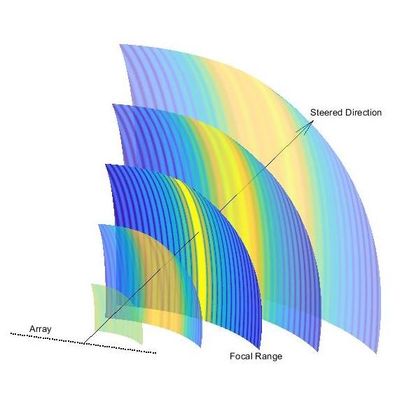
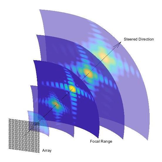
At the focal range, our beam in angle space closely resembles that of a far-field pattern.
The near/far boundary, similar in concept to other near-field/far-field boundaries, is the boundary past which focusing is not possible. Conversely, a steered but unfocused beam is not possible on the near side of the boundary. The figure below demonstrates this fact. Notice that the steered beam only begins to take shape on the far side, and the focused beam is only focused on the near side.
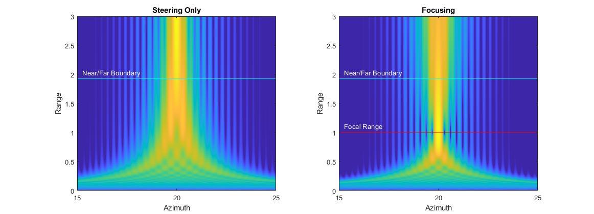
The range where this boundary can be found is well-documented in the medical imaging literature as , where is the length of the array. For a simple uniform linear array with critically-spaced elements, this can be expressed as .
Generating the Response for a Single Beam
This sections shows how to generate and plot a single beam. Start by setting up the phased array and other System objects. Common medical imaging ultrasound systems operate between 2 and 20 MHz, and the commonly-accepted average propagation speed of sound in soft tissue is 1540 m/s.
rng('default')
freq = 4e6;
c = 1540;
lambda = c/freq;
Ultrasound transducers come in a wide variety of topologies suited for specific activities. This example simply uses a uniform linear array with critical element spacing.
numElems = 256;
elemSpacing = lambda/2;
array = phased.ULA(numElems,elemSpacing);
The System objects phased.FocusedSteeringVector and phased.SphericalWavefrontArrayResponse are used in tandem to generate steered and focused element weights, and to compute the response over some domain. Pass the array and propagation speed specification from above to the constructors. For the array response, also turn on the weights input port.
SV = phased.FocusedSteeringVector('SensorArray',array,'PropagationSpeed',c);
AR = phased.SphericalWavefrontArrayResponse('SensorArray',array,'PropagationSpeed',c,'WeightsInputPort',true);
Now you have the minimal setup required to form and inspect a focused beam. Use a 10 degree steer in azimuth and a focal range of 40 mm.
azSteer = 10;
focalRange = 0.04;
Use a domain that starts in front of the array and extends out to twice the focal range, and covers the length of the array in the lateral direction. The array elements lie along the Y axis, and the array normal direction is +X.
arrayLength = numElems*elemSpacing;
x = linspace(1e-3,2*focalRange,200);
y = linspace(-arrayLength/2,arrayLength/2,200);
Convert to spherical coordinates for input to the steering vector and response computation.
[az,el,rng] = cart2sph(x,y',0);
ang = rad2deg([az(:) el(:)]');
rng = rng(:)';
Now compute the response of the focused array over the specified domain.
weights = SV(freq,[azSteer;0],focalRange);
beam = AR(freq,ang,rng,weights);
Reshape, normalize, and use log-scale.
beam = reshape(beam,numel(y),numel(x));
beam = beam/max(abs(beam(:)));
beam = mag2db(abs(beam));
Use the provided function helperPlotResponse to plot the result. The positions of the array elements are indicated by red markers.
figure
helperPlotResponse(beam,x,y,array)
title('Single Steered and Focused Beam')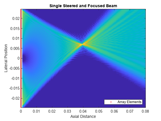
The focal region is clearly visible at the specified range and angle. As with the far-field response (pattern), the magnitude of the spherical wavefront response takes into account the varying phase across elements but, unlike the far-field response, the spherical wavefront response also includes the effect of varying free-space propagation loss across elements. This is essentially a slight amplitude modulation across elements, the effect of which is visible in the beam's sidelobes. A flat gain equal to the focal range is applied to each element, so that the overall amplitude weighting on an element is the ratio of the distance between the response point and the array center to the distance from the response point to the individual element: . For example, the contribution to the sum beam from an element located at the origin would have unit magnitude.
Focal Region
For a focal region to be bounded in range, the focal range must be small enough that the entire region (with extent determined by the DoF) must be closer than the near/far boundary. DoF can be expressed as a function of a related quantity, commonly seen in optics, known as the F-number, which is the ratio of the focal range to the length of the array: . From this quantity, a good estimate of the DoF is . For a fixed array and frequency, the DoF increases with the square of the focal range.
This section takes a look at how the DoF changes with focal range. Generate the response over an interval of focal ranges, and examine the changing DoF. The function helperPlotBeamMarkers will display an indication of the DoF for each focal range. The focal region is roughly elliptical, and is not centered on the focal range. Another rule of thumb can be used to find the offset from the focal range to the center of the region: .
nearField = arrayLength^2/(4*lambda); % Near/far boundary range

x = linspace(1e-3,nearField*1.2,100);
y = linspace(-0.01,0.01,100);

coeff = 0.1:0.1:0.9; % Proportion of near/far boundary
focalRanges = coeff*nearField;

fnum = focalRanges/arrayLength;
dof = 7.1*lambda*fnum.^2;
focalRegionCenter = focalRanges + dof/4;

figure
for ind = 1:numel(focalRanges)
    beam = helperMakeSingleBeam( SV,AR,freq,0,focalRanges(ind),x,y );
    helperPlotResponse(beam,x,y)
    caxis([-6 0]) % only view the greatest 6 dB of the beam
    helperPlotBeamMarkers(focalRanges(ind),focalRegionCenter(ind),nearField,dof(ind),0.001)
    title(sprintf('Focal Range = %d%% of Near/Far Boundary',round(coeff(ind)*100)))
    drawnow
end
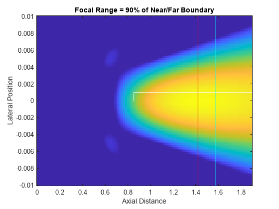
By the time the focal range has increased to 60% of the near/far boundary, the eccentricity of the focal region has become quite large. By 80%, the focal region has intersected the near/far boundary and has essentially become an unfocused beam.
Beamwidth in the focal region, as with a far-field response, may still be roughly computed with the usual , the ratio of wavelength to array length. Thus the width (in the lateral direction) of the focal region can be approximated with .
Single-Line Acquisition with Linear Subarray Shifting
A-scans and Image Formation
Unlike radar systems, where direction of arrival can be estimated efficiently through beamforming of far-field signals, the near-field beamforming and latency requirements of ultrasound systems often necessitate a simpler strategy to locate the source of returned energy. A common class of collection strategy involves multiple A-scans, reflectivity profiles along a given line segment. The placement of these lines within the formed image is determined simply by the known position of the beam.
To form a rectangular image, as is done in this example, lineary subarray shifting can be used. With this method a subset of the array elements (a subarray) is used for each pulse, with no steering, to get a range profile originating at the center of the subarray and extending in the axial direction. Successive lines are formed by shifting the subarray selection to a different set of elements.
The choice of focal range can be considered separately from beam pointing. Some systems may keep a fixed focal range, or use dynamic focusing on receive along with apodization or windowing to generate a broad image that covers much of the near-field region. In this example focal range is kept fixed while the lateral position of the subarray is varied.
The helper class helperSubarray is provided to emulate subarray selection and simplify the simulation loop. This class keeps track of which elements belong to the current subarray and handles the necessary transforms between the global and subarray frames.
Image Formation
In order to demonstrate the effects of focused beamforming, this example uses a simple image formation strategy that constructs each range profile by quantizing and accumulating the response at each pulse, then inserting that profile into the completed image based on the location of the subarray. This simulates an ideal delta pulse in free space, which allows for a comparison of lateral resolution inside and outside the focal region. This method disregards the effects of waveform choice and multipath reflections, and treats scatterers as perfect point isotropic reflectors.
Simulation
The same system parameters will be used as in the previous section. Each subarray will consist of 64 elements. The subarray starts at the end of the array and is shifted by one element on each pulse.
numSubElems = 64;
subarray = helperSubarray(array,numSubElems);
If subarray is shifted by one element on each pulse and all contiguous subarrays are covered, the total number of pulses will be
numPulses = numElems - numSubElems + 1
numPulses = 193
Following the analysis in the previous section, check the focal region parameters for this subarray. Get the subarray length, near/far boundary, DoF, and lateral width of the focal region.
subarrayLength = numSubElems*elemSpacing;
nearFieldSub = subarrayLength^2/(4*lambda); % Near/far boundary for the subarray
fnumSub = focalRange/subarrayLength;
dofSub = 7.1*lambda*fnumSub.^2
dofSub = 0.0288
widthSub = lambda/subarrayLength*focalRange
widthSub = 0.0013
The subarray beam has a DoF of about 28.8 mm, and the lateral width of the focal region is about 1.3 mm. Check that the focal region is well within the near/far boundary
boundedFocalRegion = focalRange + dofSub < nearFieldSub
boundedFocalRegion = logical
   1
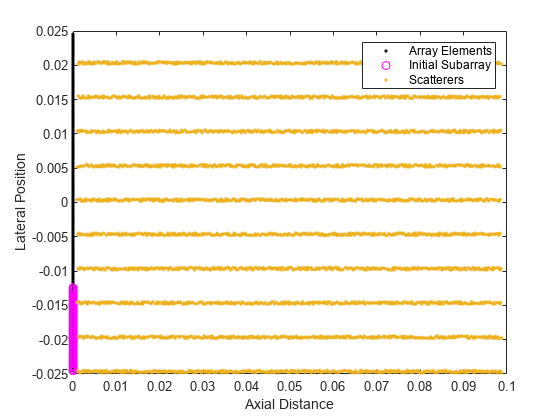
To demonstrate the primary usefulness of a focused beam, decreased beamwidth in the focal region, use multiple parallel lines of scatterers along the axial direction (depth lines). Specify the desired max depth of scatterers, and use the provided helper function, helperGetResponsePoints, to get the scatterer positions. Let all scatterers have reflectivity with unit amplitude. The scatterer positions are perturbed to avoid artifacting due to symmetry.
For the lateral spacing of the lines, use 4 times the calculated focal region width. Because the subarray is simply shifted by one element at a time, which is a shorter distance than our beam width in the focal region, return from each line of scatterers shows up in more than one row of the image, making them appear to have greater width.
maxDepth = nearFieldSub;
lineSpacing = 4*widthSub;
[sx,sy] = helperGetResponsePoints(maxDepth,arrayLength,lambda,lineSpacing);
To visualize the scene, plot the scatterer positions along with the array elements.
figure
plot(subarray)
hold on
plot(sx,sy,'.')
hold off
legend('Array Elements','Initial Subarray','Scatterers')
xlabel('Axial Distance')
ylabel('Lateral Position')
To form a range profile and capture the effects of interference from sidelobe return, range sampling parameters must be defined. Modern ultrasound systems use a relatively high sampling frequency, on the same order as the center frequency of the transmitted waveform. Use a range bin size of 1 mm, corresponding to a sampling rate of about 1.5 MHz. The provided helper function helperFormRangeProfile is used to form the range profile from the array response data.
rangeBinSize = 1e-3;
Fs = c/rangeBinSize;
rangeBins = 0:rangeBinSize:maxDepth;
numRangeSamples = numel(rangeBins);
Get the scatterer positions in spherical coordinates (angles in degrees) for input to SphericalWavefrontArrayResponse.
[respAng,~,respRng] = cart2sph(sx,sy,0);
respAng = rad2deg(respAng(:)');
respRng = respRng(:)';
Each loop of the simulation involves computing weights for the current subarray, computing the response, forming a range profile, and forming the image line by line. We'll also apply range-dependent gain for uniform brightness (see helperFormRangeProfile).
im = zeros(numPulses,numRangeSamples);
center = zeros(3,numPulses);

for pulse = 1:numPulses

    center(:,pulse) = subarray.center; % Center position of our current subarray
    [focAzGlobal,~,focRngGlobal] = subarray.localToGlobalSph( 0,0,focalRange ); % Angle and range to current focal point

    weights = SV(freq,[focAzGlobal;0],focRngGlobal);
    weights(~subarray.selection) = 0; % Zero-out weights for unused elements

    resp = AR(freq,respAng,respRng,weights);
    resp = resp./respRng(:); % Undo normalization to use actual propagation loss

    im(pulse,:) = helperFormRangeProfile(resp,sx,sy,center(:,pulse),rangeBins); % Add line to image

    if pulse < numPulses
        subarray.shift(1) % Shift subarray if there are pulses remaining
    end

end
Normalize and plot the image, along with an overlay of the scatterer positions.
im = im/max(abs(im(:)));
figure
subplot(1,2,1)
helperPlotResponse(mag2db(abs(im)),rangeBins,center(2,:))
title('Linear Subarray Shift Image')
subplot(1,2,2)
helperPlotResponse(mag2db(abs(im)),rangeBins,center(2,:))
hold on
plot(sx,sy,'.r','markersize',1)
hold off
title('Scatterer Overlay')
set(gcf,'Position',get(gcf,'Position')+[0 0 560 0]);
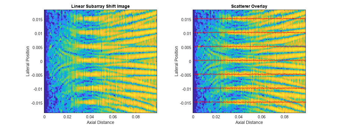
The depth lines are resolvable about the focal range, over a range interval roughly equal to the computed DoF for the subarray beam. Away from the focal point, the parallel lines of scatterers quickly become indistinguishable thanks to the wide angular spread of the beam outside the focal region.
Note that, though all the scatterers were used to compute energy return, not all lines are visible due to the clipping between the full array size and the extent of subarray center positions. A wider total field of view would be obtainable with a shorter subarray, at the cost of reduced lateral resolution.
Conclusion
This example introduced two System objects for computing focused weights and for computing the non-far-field response of an array with spherical wavefronts. It showed how to examine some basic characteristics of a focused beam, and how to generate a basic image to visualize the effect of a focused beam on lateral resolution with a linear subarray shift collection method.
References
[1] Demi, Libertario. “Practical Guide to Ultrasound Beam Forming: Beam Pattern and Image Reconstruction Analysis.” Applied Sciences 8, no. 9 (September 3, 2018): 1544. https://doi.org/10.3390/app8091544
[2] Ramm, O. T. Von, and S. W. Smith. “Beam Steering with Linear Arrays.” IEEE Transactions on Biomedical Engineering BME-30, no. 8 (August 1983): 438–52.
Helper Functions
helperMakeSingleBeam
function [beam,x,y] = helperMakeSingleBeam( SV,AR,freq,azSteer,focalRange,x,y )
% Get the element weighting for a single beam and compute the response

weights = SV(freq,[azSteer;0],focalRange);

% Domain of response
if nargin < 6
    x = linspace(1e-3,2*focalRange,200);
end
if nargin < 7
    pos = SV.SensorArray.getElementPosition;
    halfy = max(pos(2,:))*1.2;
    y = linspace(-halfy,halfy,200);
end
[az,el,rng] = cart2sph(x,y',0);
ang = rad2deg([az(:) el(:)]');
rng = rng(:)';

% Generate response
beam = AR(freq,ang,rng,weights);
beam = reshape(beam,numel(y),numel(x));

% Normalize and use log scale
beam = beam/max(abs(beam(:)));
beam = mag2db(abs(beam));

end
helperPlotResponse
function helperPlotResponse(R,x,y,array)
% Plot the response, R, on the domain defined by x and y.

imagesc(x,y,R)
set(gca,'ydir','normal')
caxis([-32 0])
xlabel('Axial Distance')
ylabel('Lateral Position')

if nargin > 3
    pos = getElementPosition(array);
    hold on
    h = plot(pos(1,:),pos(2,:),'.r');
    hold off
    xl = xlim;
    xlim([min(pos(1,:)) xl(2)])
    legend(h,'Array Elements','Location','southeast','AutoUpdate','off')
end

end
helperPlotBeamMarkers
function helperPlotBeamMarkers(focalRange,center,nearField,dof,offset)
% Put informative markers on a beam plot

line([center-dof/2 center+dof/2],[offset offset],'color','white')
line([center-dof/2 center-dof/2],[0 offset],'color','white')
line([center+dof/2 center+dof/2],[0 offset],'color','white')

line([focalRange focalRange],ylim,'color','red')
line([nearField nearField],ylim,'color','cyan')

end
helperGetResponsePoints
function [sx,sy] = helperGetResponsePoints( maxDepth,arrayLength,lambda,dy )
% Make parallel lines of scatterers along X

sx = linspace(0.001,maxDepth,400);
sy = -arrayLength/2:dy:arrayLength/2;

[sx,sy] = meshgrid(sx,sy);
sx = sx(:);
sy = sy(:);

sx = sx + (rand(size(sx))-1/2)*lambda;
sy = sy + (rand(size(sy))-1/2)*lambda;

end
helperFormRangeProfile
function rangeProf = helperFormRangeProfile(resp,sx,sy,center,rangeBins)
% This helper function quantizes a response in range, coherently
% accumulates the return in each bin, and applies amplitude weighting per
% range bin

rangeBinSize = rangeBins(2) - rangeBins(1);
numRangeSamples = numel(rangeBins);

% Range of scatterers relative to subarray center
scatRngRel = sqrt((center(1)-sx).^2 + (center(2)-sy).^2);

% Quantize scatterer ranges into fast-time sampling vector
scatRidx = 1 + floor(scatRngRel/rangeBinSize);

% Only keep samples below max depth
I = scatRidx <= numRangeSamples;
scatRidx = scatRidx(I);
resp = resp(I);

% Accumulate return into fast-time sampling grid
rangeProf = accumarray(scatRidx,resp,[numRangeSamples 1]);
rangeProf = rangeProf';

% Apply range-dependent gain
rangeProf = rangeProf.*rangeBins;

end
helperPlotULAWavefronts
function helperPlotULAWavefronts( numElems,f,c,az,r )
% Plot the wavefronts for the given ULA with ArrayAxis 'y', for the given
% azimuth angle and focal range.
%
% For the far-field wavefront, use inf for focal range

lambda = c/f;
array = phased.ULA(numElems,lambda/2);
pos = getElementPosition(array);
arrayLength = max(pos(2,:)) - min(pos(2,:));

% get relative path lengths
if isinf(r)
    L = phased.internal.elemdelay(pos,c,[az;0])*c;
else
    L = phased.internal.sphericalelemdelay(pos,c,[az;0],r)*c;
end

% plot element positions
plot(pos(1,:),pos(2,:),'oblue');
hold on;

% if near field, plot source
if ~isinf(r)
    [src(1,1),src(2,1),src(3,1)] = sph2cart(az*pi/180,0,r);
    plot(src(1),src(2),'*r','markersize',10);
end

% wavefront marker width
s = lambda/6;

% far field prop path
if isinf(r)
    [los(1,1),los(2,1),los(3,1)] = sph2cart(az*pi/180,0,1);
end

for ind = 1:size(pos,2) % for each element

    p = pos(:,ind);

    if isinf(r)
        src = p + los*arrayLength;
    end

    path = src - p;
    path = path/norm(path);

    wp = p + path*L(ind); % position of wavefront

    % prop path
    line([wp(1) src(1)],[wp(2) src(2)],'color','black','linestyle','--');

    % wavefront marker
    u = cross([0;0;1],path)*s;
    line([wp(1)-u(1) wp(1)+u(1)],[wp(2)-u(2) wp(2)+u(2)],'color','magenta');

end

hold off;
grid on;
axis equal;

if isinf(r)
    legend('Elements','Prop Path','Wavefronts','Location','SouthEast');
else
    legend('Elements','Focal Point','Prop Path','Wavefronts','Location','SouthEast');
end

end
helperPlotResponseSlices
function helperPlotResponseSlices
% Demonstrates how to visualize range slices of a spherical wavefront response

f = 2e6;
c = 1540;
lambda = freq2wavelen(f,c);

array = phased.URA([32 32],lambda/2);
elemPos = array.getElementPosition;

focalRange = 0.03;
sampleRanges = .01:.01:.05;

% domain of each slice
azSteer = -20;
elSteer = 20;
az = azSteer + (-30:.1:30);
el = elSteer + (-30:.1:30);
[az,el] = meshgrid(az,el);
ang = [az(:) el(:)]';
[x,y,z] = sph2cart(az*pi/180,el*pi/180,1);

SV = phased.FocusedSteeringVector('SensorArray',array,'PropagationSpeed',c);
AR = phased.SphericalWavefrontArrayResponse('SensorArray',array,'PropagationSpeed',c,'WeightsInputPort',true);

w = SV(f,[azSteer;elSteer],focalRange);

for ind = 1:numel(sampleRanges)
    resp = AR(f,ang,sampleRanges(ind),w);
    resp = resp / array.getNumElements;
    resp = reshape(resp,size(x));
    alpha = 1 - (abs(sampleRanges(ind) - focalRange)/(max(sampleRanges)-min(sampleRanges))); % transparency

    surf(x*sampleRanges(ind),y*sampleRanges(ind),z*sampleRanges(ind),mag2db(abs(resp)),'FaceAlpha',alpha)
    hold on
    shading flat
end

% plot element positions and boresight vector
caxis([-32 0])
plot3(elemPos(1,:),elemPos(2,:),elemPos(3,:),'.black','markersize',4);
[b(1),b(2),b(3)] = sph2cart(azSteer*pi/180,elSteer*pi/180,max(sampleRanges)*1.2);
quiver3(0,0,0,b(1),b(2),b(3),'black','autoscale','off')
axis equal
axis off
hold off
set(gca,'view',[-70 22])

end
