Estimate Initial Rotor Position Using Pulsating High-Frequency and Dual-Pulse Methods
This example estimates the initial position (in electrical radians) of a stationary interior PMSM by using pulsating high-frequency (PHF) injection and dual pulse (DP) techniques.
The example determines the best possible initial estimation for the rotor position using open-loop PHF injection, which it uses for running closed-loop PHF.
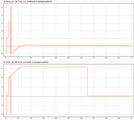
It executes closed-loop PHF by injecting a high-frequency signal into the estimated rotor position to determine the actual rotor position without spinning the motor. This technique works when the motor has a saliency ratio (Lq/Ld) greater than 1. Due to a limitation in the PHF method, the estimated position can show ambiguity of π(pi). The dual-pulse (DP) method uses polarity detection to resolve the ambiguity of π and applies π compensation if there is an error. The estimated rotor position ranges from 0 to 2π electrical radians.
The example uses the Pulsating High Freq Observer block to implement the position estimation algorithm. For more details, see Pulsating High Freq Observer.
The example runs only for Stage 1, initial position estimation (IPE) (as described in the Pulsating High Freq Observer block page), and includes three parts.
Stage 1 focuses on determining the initial position of a stationary rotor.
Note: Stage 2 is an extended operation mode where you can use this technique to compute the rotor position when the motor is running using closed loop control. This example does not cover Stage 2.
Model
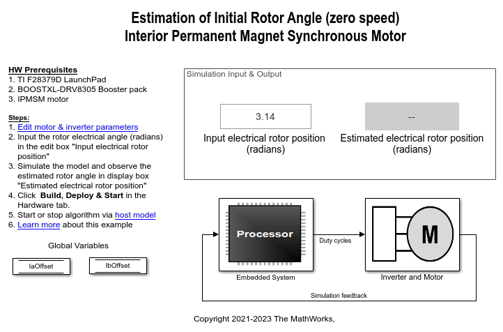
The example includes the target model mcb_ipmsm_pos_est_f28379d.
You can simulate this model or run it on the hardware.
Required bat365 Products
Motor Control Blockset™
Embedded Coder®
C2000™ Microcontroller Blockset
Simscape™ Electrical™ (only for simulation)
Prerequisites
1. Determine the motor parameters. The target model uses default parameters, which you can replace with values from the motor datasheet or other sources.
However, if you have motor control hardware, you can estimate the parameters for your motor by using the Motor Control Blockset parameter estimation tool. For instructions, see Estimate PMSM Parameters Using Recommended Hardware. The parameter estimation tool updates the motorParam variable (in the MATLAB® workspace) with the estimated motor parameters.
2. Update the motor and inverter parameters in the model initialization script associated with the target model. For instructions, see Estimate Control Gains and Use Utility Functions.
Simulate Model
Follow the instructions in the Simulate Nonlinear Stator Core Behavior section to introduce high saliency in the motor block. Then follow these steps to simulate the target model.
1. Open the target model included in this example.
2. Enter the initial rotor position value (that the Interior PMSM block should use for simulation) in the Input electrical rotor position (radians) field available in the Simulation Input & Output area of the target model.
3. Click Run on the Simulation tab to simulate the target model. The model estimates the rotor position using the PHF method. Then it uses the DP method to determine if the estimated rotor position needs π compensation. The target model applies π compensation if needed.
It then displays the estimated rotor position in the Estimated electrical rotor position (radians) field.
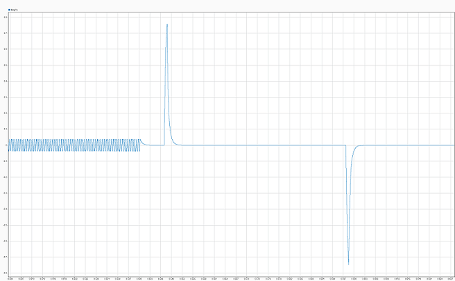
4. Observe the logged signals in the Simulation Data Inspector.
This plot shows the current along the d-axis  during simulation.
This plot shows the estimated rotor position when the target model does not apply π compensation  and when the target model applies π compensation
  .
.
5. The Estimated Rotor Position (Electrical Radians) display block in the Output area of the target model shows the initial rotor position estimated by the target model.
Generate Code and Deploy Model to Target Hardware
Follow the instructions in this section to generate code and run the example on the target hardware.
This example uses a host and a target model. The host model is a user interface to the controller hardware board. You can run the host model on the host computer. Before you run the host model on the host computer, deploy the target model to the controller hardware board. The host model uses serial communication to command the target Simulink® model and run the motor in closed-loop control.
Required Hardware
The example supports this hardware configuration. You can also use the target model name to open the model from the MATLAB® command prompt.
LAUNCHXL-F28379D controller + BOOSTXL-DRV8305 inverter + iPMSM (such as Adlee BM-180 motor): mcb_ipmsm_pos_est_f28379d
For connections related to this hardware configuration, see LAUNCHXL-F28069M and LAUNCHXL-F28379D Configurations.
Generate Code and Run Model on Target Hardware
1. Simulate the target model and observe the simulation results.
2. Complete the hardware connections.
3. By default, the model computes the ADC offset values for phase current measurement. To disable this functionality, update the value of the inverter.ADCOffsetCalibEnable variable in the model initialization script to 0.
Alternatively, you can compute the ADC offset values and update them manually in the model initialization script. For instructions, see Run 3-Phase AC Motors in Open-Loop Control and Calibrate ADC Offset.
4. Open the target model. If you want to change the default hardware configuration settings for the model, see Model Configuration Parameters.
5. Load a sample program to CPU2 of the LAUNCHXL-F28379D board. For example, load the program that operates the CPU2 blue LED by using GPIO31 (c28379D_cpu2_blink.slx). This ensures that CPU2 is not mistakenly configured to use the board peripherals intended for CPU1. For more information about the sample program or model, see the Task 2 - Create, Configure and Run the Model for TI Delfino F28379D LaunchPad (Dual Core) section in Getting Started with Texas Instruments C2000 Microcontroller Blockset (C2000 Microcontroller Blockset).
6. Click Build, Deploy & Start on the Hardware tab to deploy the target model to the hardware. Verify the variables that the target model adds to the workspace.
7. Click the host model hyperlink in the target model to open the associated host model.
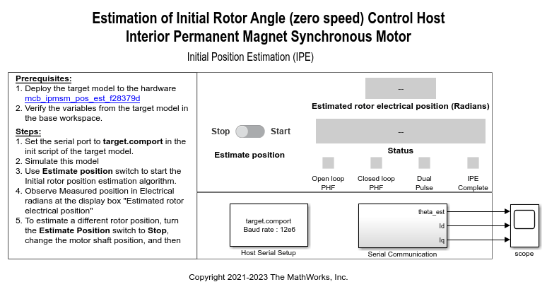
For details on serial communication between the host and target models, see Host-Target Communication.
8. In the model initialization script associated with the target model, specify the communication port using the variable target.comport. The example uses this variable to update the Port parameter of the Host Serial Setup, Host Serial Receive, and Host Serial Transmit blocks available in the host model.
9. Click Run on the Simulation tab to run the host model.
10. Change the position of the Estimate Position switch to Start to start running the example algorithm. The target model estimates the rotor position using PHF method. Then it uses the DP method to determine if the estimated rotor position needs π compensation. The target model applies π compensation if needed.
The host model obtains the estimated rotor position from the target hardware and displays it in the Estimated rotor electrical position (radians) field.
11. To estimate a different rotor position, change the position of the Estimate Position switch to Stop. The Estimated rotor electrical position (radians) field displays the value 0.
Turn the motor shaft to a new position. Then change the position of the Estimate Position switch to Start to run the example algorithm again and estimate the new position.
12. Observe the estimated position, Id, and Iq signals in the time scope available in the host model.
This plot shows the estimated rotor electrical position ( ) and the stator currents (
Id) and (Iq).
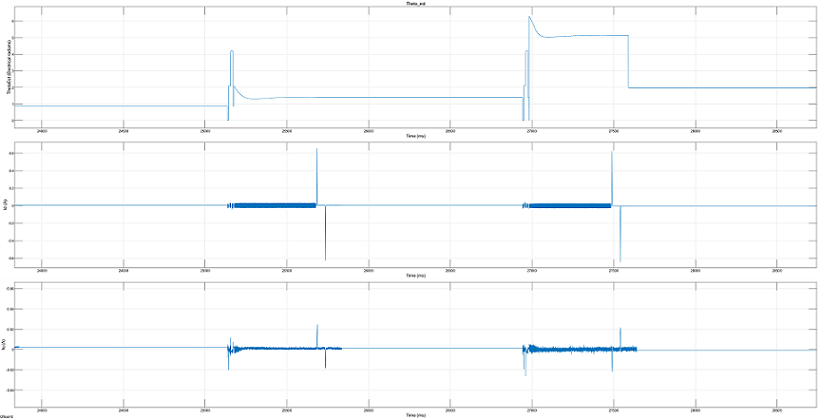
13. The Status field displays the following statuses:
"IPE not started" — Stage 1 operation not yet started.
"IPE running" — Stage 1 operation is presently running.
"IPE completed" — Stage 1 operation is complete.
"IPE failed" — Stage 1 operation failed due to a high error in estimated position.
Simulate Nonlinear Stator Core Behavior
The DP method algorithm works only when the stator core saturates and shows a nonlinear behavior. To generate this behavior in simulation, the target model uses the PMSM (Simscape Electrical) block from Simscape™ Electrical™. Follow this procedure to experimentally determine the tabulated  ,
,  , and
, and  data for the actual motor, and use this data to make the motor block nonlinear for simulation purposes.
Determine ${L_d}$ Data
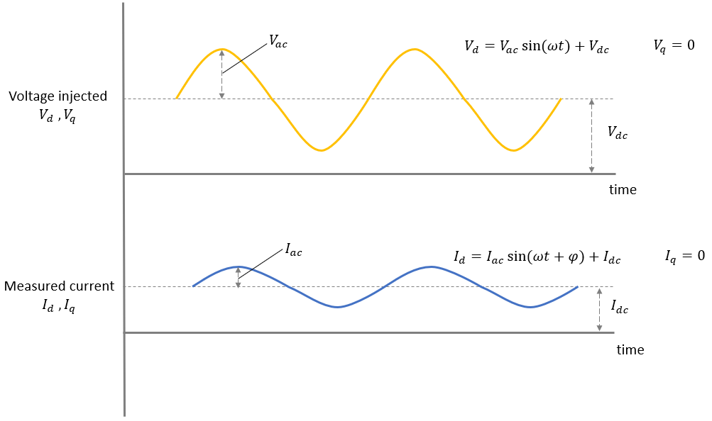
1. Create a target model to run a PMSM using open-loop control. Modify the algorithm so that it injects the voltages  and
and  into the actual motor. This generates the current
  in the motor where:
 is the voltage that the algorithm computes and injects along the rotor's d-axis.
 is the frequency at which you can measure the phase difference. This frequency should be approximately 10 times lower than the PWM switching frequency but should be high enough to keep the rotor stationary (a frequency value that is too low can spin the rotor).
 is the AC component of
  (such that
  and ω are constants that the algorithm can assume).
 is the DC component of
  that you provide as an input.
 is the current along the d-axis of the rotor that the algorithm computes from the measured
  and
and  phase currents.
 is the AC component of
  (ϕ is the phase difference between
  and
and  that the algorithm should measure).
 is the DC component of
  , which is fixed for a
  input (the algorithm should compute this value by using
  and the motor resistance).
Note: Because  , the rotor remains stationary.
a. Add an algorithm to read the  and
and  phase currents that the motor draws.
b. Add an algorithm to convert the  and
and  phase current values into the equivalent
  value by using Clarke and Park transforms.
c. Add an algorithm to compute ϕ and  .
.
d. Add an algorithm to compute  .
.

e. Add an algorithm to compute  .
.
 (for a fixed
  )
)
For details about designing a control algorithm and configuring it for deployment to the target hardware, see Control Algorithm Design and Deployment and Validation.
2. Create a model initialization script (.m file) to initializate the parameters and perform other calculations. Use the Model Properties > Callbacks to integrate this script with the target model. For details about how to use this script with Motor Control Blockset™, see Estimate Control Gains and Use Utility Functions.
3. Configure the target model to run on the target hardware. For instructions, see Model Configuration Parameters.
4. Create a separate host model to control and communicate with the target model running on the motor-control hardware in real time. You can add an Edit box on the host model and use it to send  input to the target hardware. Use Display boxes to obtain the computed
  and
and  values from the target hardware.
For details about the host-target communication interface, see Host-Target Communication.
5. Click Build, Deploy & Start on the Hardware tab to deploy the target model to the hardware.
6. Simulate the host model. Send a  input to the target hardware and record the
  and
and  values that you obtain.
7. Change  manually across a range between a negative and positive voltage and record the resulting
  and
and  values for each operating point.
Determine ${L_q}$ Value
Perform these steps to determine a  value that is higher than the sequence of
  values obtained from the Determine Ld section. This is necessary to maintain a high saliency ratio (
 ) for the simulated motor block.
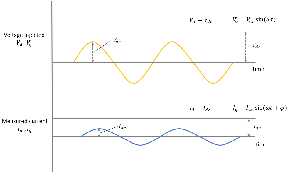
1. Modify the target model that you used in the Determine Ld section so that it injects the voltages  and
and  into the actual motor. This generates a current
  in the motor where:
 is the constant DC voltage that the algorithm injects along the d axis of the rotor.
  should be high enough to hold the rotor at zero position and keep it stationary.
 is the AC voltage that the algorithm computes and injects along the q-axis of the rotor. (such that
  and ω are constants that the algorithm assumed in the Determine Ld section)
 is the AC current along the
 q-axis of the rotor that the algorithm computes from the measured  and
and  phase currents (ϕ is the phase difference between
  and
and  that the algorithm should measure)
a. Update the existing algorithm to convert the  and
and  phase current values into the equivalent
  value by using Clarke and Park transforms.
b. Update the existing algorithm to compute ϕ.
c. Update the existing algorithm to compute  .
.

d. Add an algorithm to compute  .
.

2. Update the model initialization script to perform the preceding modified calculations.
3. Update the host model to obtain and display the  value computed by the target hardware.
4. Click Build, Deploy & Start on the Hardware tab to deploy the target model to the hardware.
5. Simulate the host model. Send a  input to the target hardware and record the
  value that you obtain.
Design High Saliency Motor Block
The Determine Ld Data and Determine Lq Value sections in this page provide the following data:
Sequence of
 values
Sequence of
 (
( for a DC current) values
Constant
 value
value
In addition, you can assume a set of  values to add high saliency to the motor block.
Use the variables pmsm.nonlin.idVec, pmsm.nonlin.Ld_data, pmsm.nonlin.iqVec, and pmsm.nonlin.Lq_data to store this data in the model initialization script mcb_ipmsm_pos_est_f28379d_data.m associated with the example target model mcb_ipmsm_pos_est_f28379d.slx.
Note: This script is different from the model initialization script used in the Determine Ld Data and Determine Lq Value sections.
In addition, define the pmsm.nonlin.LdMatrix, pmsm.nonlin.LqMatrix, and pmsm.nonlin.PmMatrix variables.
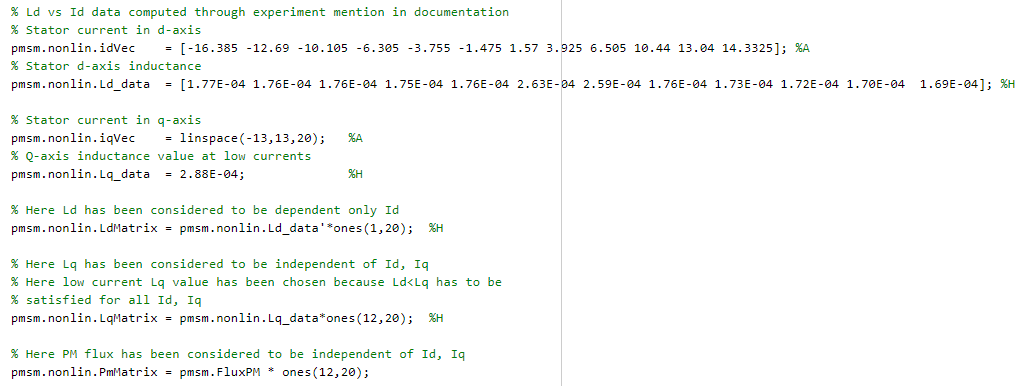
In the PMSM (Simscape Electrical) block parameter dialog box, set the Modeling fidelity parameter to Tabulated Ld, Lq and PM and add the variables as shown in the following figure.
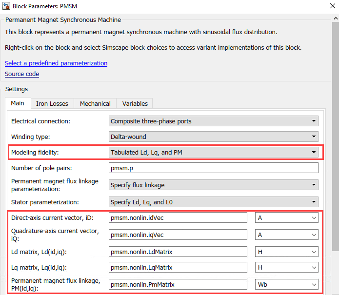
The variables pmsm.nonlin.idVec, pmsm.nonlin.Ld_data, pmsm.nonlin.iqVec, and pmsm.nonlin.Lq_data help saturate the stator core and introduce nonlinear behavior during simulation. This enables the algorithm in the DP method to generate the  current impulses (corresponding to Pulse-1 and Pulse-2) with different peaks.
References
[1] W. Zine, L. Idkhajine, E. Monmasson, Z. Makni, P. Chauvenet, B. Condamin, and A. Bruyere, "Optimisation of HF signal injection parameters for EV applications based on sensorless IPMSM drives", IET Electric Power Applications, Volume 12, Issue 3, March 2018, p. 347 - 356 (doi:10.1049/iet-epa.2017.0228).
[2] Gaolin Wang, Guoqiang Zhang, and Dianguo Xu, "Position Sensorless Control Techniques for Permanent Magnet Synchronous Machine Drives", Springer, Singapore, 2020 p. 41 - 43 (doi: https://doi.org/10.1007/978-981-15-0050-3).
