Code Generation for Interpolated FIR Filter
Design and implement a high-order FIR filter efficiently using a cascade of multirate multistage filters. Generate and customize the generated C code from the filters.
Required bat365™ products:
MATLAB®
DSP System Toolbox™
Simulink®
MATLAB® Coder™
Simulink® Coder™
Embedded Coder™
Introduction
You can efficiently implement higher order FIR filters using multirate multistage approaches. To reduce the cost of implementation, you can split a single-stage higher order into a cascade of lower order multirate filters.
The interpolated FIR (ifir) in this example uses a cascade of FIR decimator, FIR filter, and FIR interpolator whose coefficients can be adjusted to achieve a desired frequency response. For code generation, the coefficient variables are named and placed in files such that they could be accessed by other software components that dynamically change the coefficients while running on the target processor.
The following sections describe how to specify the interpolated FIR design, how to explore the behavior through simulation, and how to generate and customize the generated code.
Specify Design
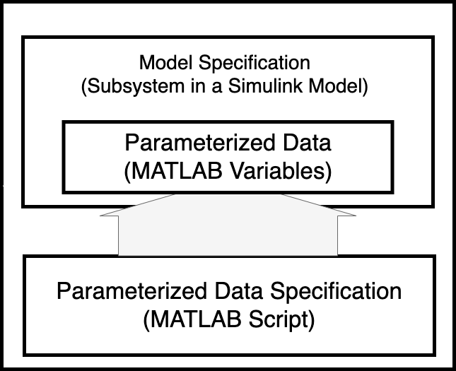
The interpolated FIR design and implementation algorithm is specified in two parts: a model specification and a parameterized data specification. The model specification is a Simulink subsystem that specifies the signal flow of the algorithm. The model specification also accesses parameterized data that exists in the MATLAB workspace. The parameterized data specification is a MATLAB script that creates the data that is accessed by the Simulink model.
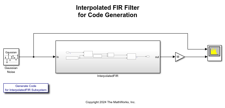
For this example, the model specification is the InterpolatedFIR subsystem of the Simulink model dspifircodegen. In this subsystem, the input is passed through a cascade of FIR decimation, FIR filtering and FIR interpolation.
For this example, the parameterized data specification is the MATLAB script dapifirdata.m. This MATLAB script specifies the initial filter coefficients as well as code generation attributes. When you open the model dspifircodegen, the model's PreLoadFcn callback is configured to run the dspifirdata.m script that creates the parameter data in the MATLAB workspace.

Explore Behavior Through Simulation
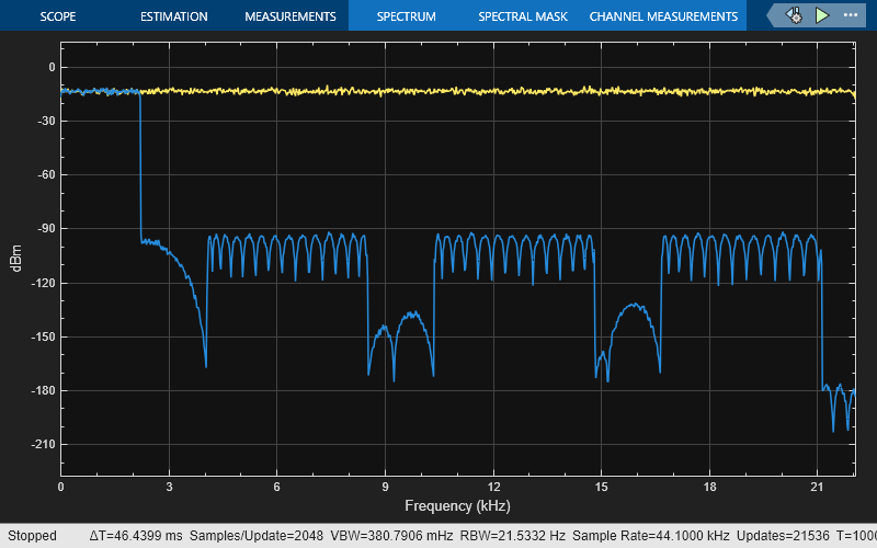
You can simulate the model to explore the behavior of the interpolated FIR design and implementation. The model uses a Spectrum Analyzer block to view the magnitude response. Click Run in the Simulation tab to run the model. The simulation time is set to 1000 sec.
Generate C Code for Interpolated FIR Subsystem
Once you achieve the desired simulation behavior, you can generate C code for the InterpolatedFIR subsystem based on the design specification. The model used in this example is configured to show some common code generation customizations accessible from the Embedded Coder product. These customization simplify the code review and integration process. The following sections show how to apply some of the code customization to this model and provide links to documentation that describes these customizations in more detail.
To generate C code, right-click the InterpolatedFIR subsystem, select C/C++ Code > Build This Subsystem . You can also generate code by clicking this hyperlink: Generate Code for the InterpolatedIFIR Subsystem.
Code Generation Report with Bidirectional Linking
The model is configured to generate an HTML report that you can use to navigate the generated source and header files. The report also enables bidirectional linking between the generated code and the model.
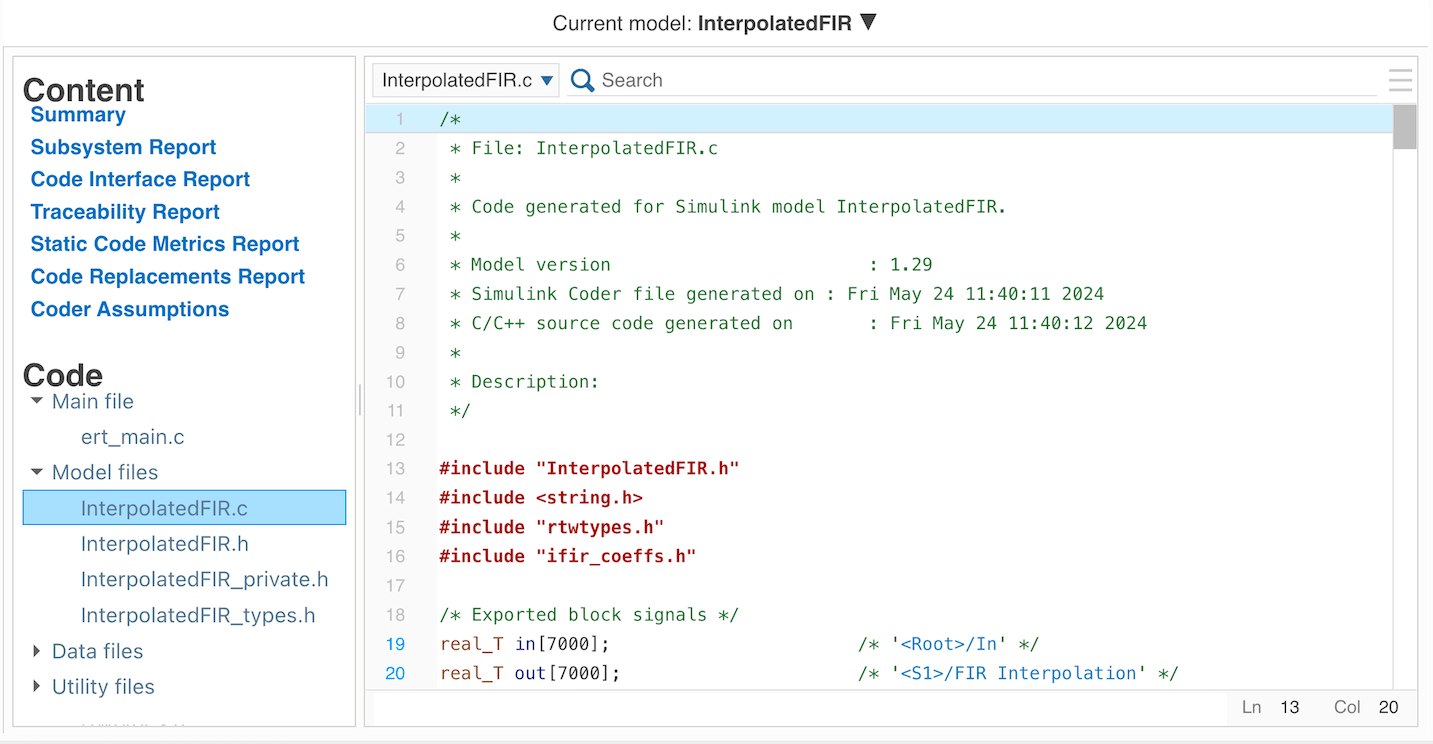
For more information on traceability between the model and code, see Trace Simulink Model Elements in Generated Code (Embedded Coder).
Call Generated Code
You can integrate the generated code into an application by making calls to the model initialization and model step functions. You can see how to call the generated code by looking at the generated example ert_main.c file. Note that the example main() in ]ert_main.c] calls InterpolatedFIR_initialize() to initialize states. The example code rt_OneStep() in ert_main.c shows how a periodic mechanism such as an interrupt calls InterpolatedFIR_step() from the file InterpolatedFIR.c.
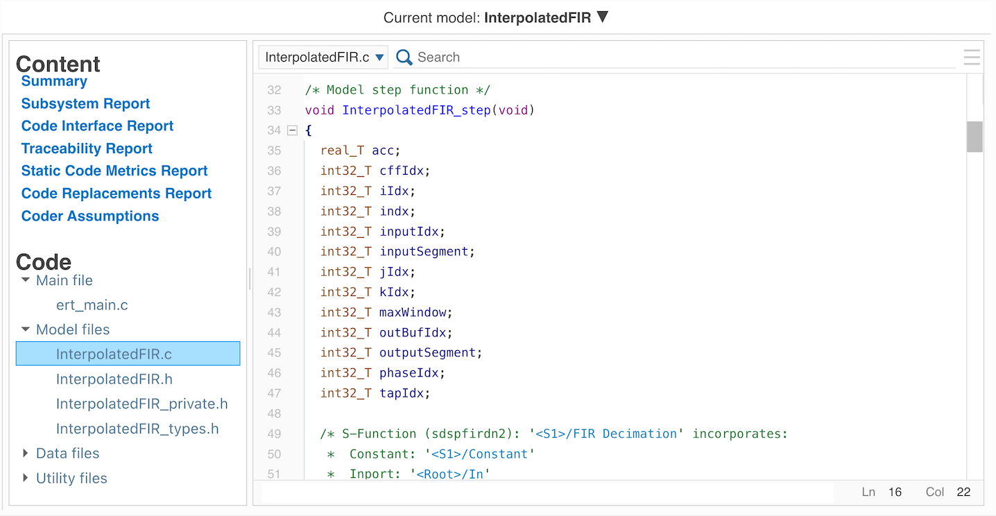
For more information about how to integrate generated code into another application see Deploy Applications to Target Hardware (Embedded Coder).
Input and Output Data Interface
The parameterized data specification file, dspifirdata.m, creates in and out signal data objects in the MATLAB workspace. These data objects are associated with signal lines in the model and are used to specify descriptions and storage classes of the corresponding variables in the generated code. For example, the signals in and out are declared as global variables in InterpolatedFIR.c. To run the model step function, an application writes data to in, calls the InterpolatedFIR_step() function, and then reads the results from out.
For more information on data objects, see Create Data Objects for Code Generation with Data Object Wizard (Embedded Coder).
Text Annotations in Code Comments
You can insert design documentation entered as text in the model as comments in the generated code. The InterpolatedFIR subsystem contains annotation text with the keyword S:Description. The code generator identifies that the text starts with this keyword and inserts the text following the keyword as comments into the generated code.
For more information on inserting annotation text into code comments, see Add Global Comments in the Generated Code (Embedded Coder).
Coefficient File Placement
The parameterized data specification file, dspifirdata.m, creates parameter data objects for the coefficients in the MATLAB workspace. These data objects are configured to define and declare coefficient variables in separate files ifir_coeffs.c and ifir_coeffs.h, respectively. Partitioning coefficients into separate files enables other software components to access this data. For example, in a deployed application, you can schedule another software component to modify these variables at runtime before they are used by InterpolatedFIR_step().
For more information about file placement of data objects, see Control Placement of Global Data Definitions and Declarations in Generated Files (Embedded Coder).
Filter Design Parameters in Coefficient Variable Comments
When coefficients are calculated (in the parameterized data file), the filter design parameters are stored in the Description field of the coefficient parameter data objects. The model is configured to insert the design parameters as comments in the generated code. This enables reviewers of the code to easily identify design parameters used to design the filters.
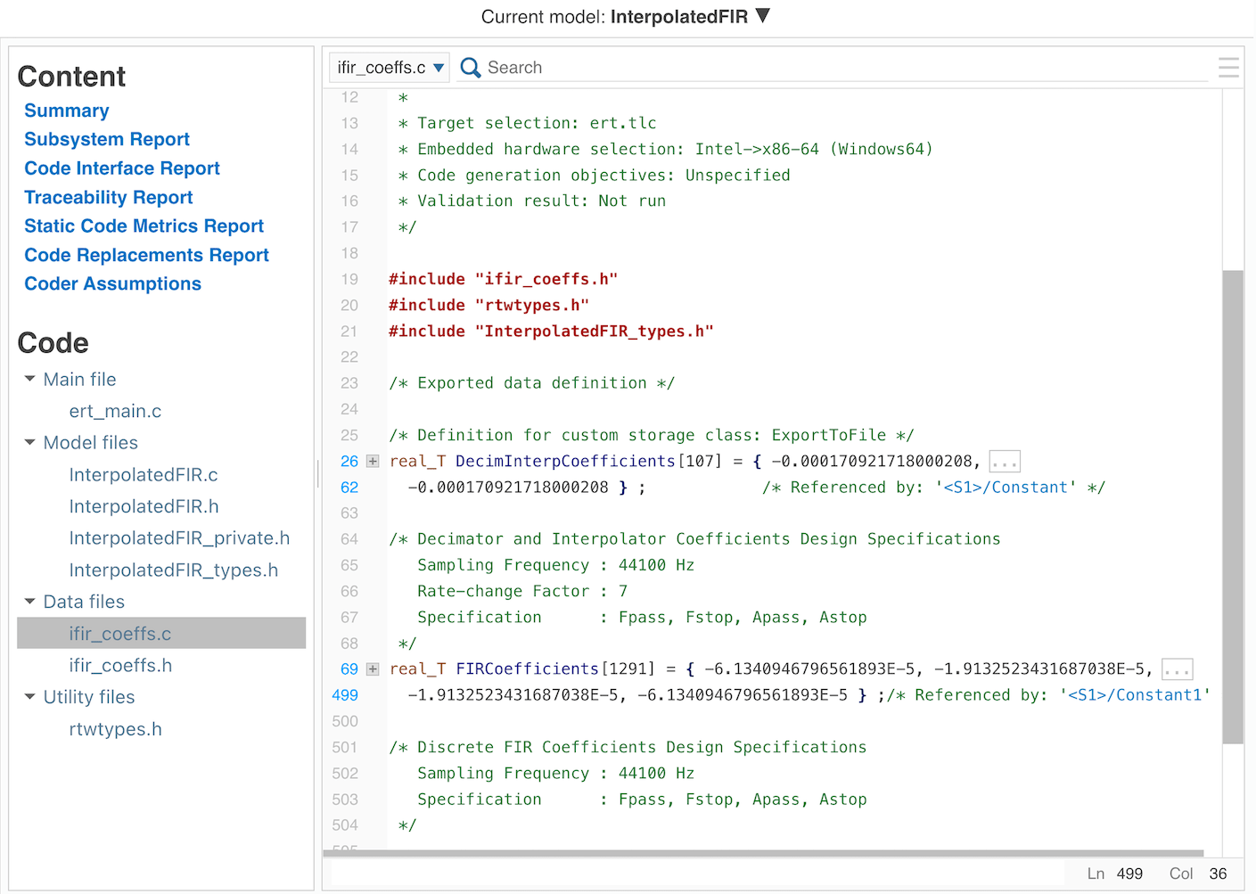
For more information on customizing the comments of data objects in the generated code, see Add Custom Comments for Variables in the Generated Code (Embedded Coder).
Package Generated Files
The generated files referenced by the HTML report exist in the InterpolatedFIR_ert_rtw directory. In addition to the files in this directory, other files in the MATLAB application install directory may be required for integration into a project. To ease porting the generated code to other environments, this model is configured to use the PackNGo feature, which packages all the required files into the zip file InterpolatedFIR.zip. Note that the zip file contains all of the required files, but might also contain additional files that may not be required.
For more information on packaging files for integration into other environments, see Relocate or Share Generated Code (Simulink Coder).
See Also
Random Source | FIR Decimation | Discrete FIR Filter (Simulink) | FIR Interpolation | Spectrum Analyzer
Related Topics
- Generate and Deploy SIMD Optimized Code for Interpolated FIR Filter on Intel Desktops
- Generate Standalone Executable and Interact with It Using UDP
- Trace Simulink Model Elements in Generated Code (Embedded Coder)
- Create Data Objects for Code Generation with Data Object Wizard (Embedded Coder)
- Add Global Comments in the Generated Code (Embedded Coder)
- Control Placement of Global Data Definitions and Declarations in Generated Files (Embedded Coder)
- Add Custom Comments for Variables in the Generated Code (Embedded Coder)
- Relocate or Share Generated Code (Simulink Coder)
