Generate Voltage Signals Using NI Devices
This example shows how to generate data using a National Instruments device.
Discover Devices That Can Output Voltage
To discover a device that supports analog outputs, access the device in the table returned by the daqlist command. This example uses an NI 9263 module in National Instruments® CompactDAQ Chassis NI cDAQ-9178. This is module 2 in the chassis.
d = daqlist("ni")
d =

  12×4 table

     DeviceID                 Description                    Model             DeviceInfo
    ___________    __________________________________    _____________    ____________________

    "cDAQ1Mod1"    "National Instruments NI 9205"        "NI 9205"        [1×1 daq.DeviceInfo]
    "cDAQ1Mod2"    "National Instruments NI 9263"        "NI 9263"        [1×1 daq.DeviceInfo]
    "cDAQ1Mod3"    "National Instruments NI 9234"        "NI 9234"        [1×1 daq.DeviceInfo]
    "cDAQ1Mod4"    "National Instruments NI 9201"        "NI 9201"        [1×1 daq.DeviceInfo]
    "cDAQ1Mod5"    "National Instruments NI 9402"        "NI 9402"        [1×1 daq.DeviceInfo]
    "cDAQ1Mod6"    "National Instruments NI 9213"        "NI 9213"        [1×1 daq.DeviceInfo]
    "cDAQ1Mod7"    "National Instruments NI 9219"        "NI 9219"        [1×1 daq.DeviceInfo]
    "cDAQ1Mod8"    "National Instruments NI 9265"        "NI 9265"        [1×1 daq.DeviceInfo]
    "Dev1"         "National Instruments PCIe-6363"      "PCIe-6363"      [1×1 daq.DeviceInfo]
    "Dev2"         "National Instruments NI ELVIS II"    "NI ELVIS II"    [1×1 daq.DeviceInfo]
    "Dev3"         "National Instruments PCIe-6363"      "PCIe-6363"      [1×1 daq.DeviceInfo]
    "Dev4"         "National Instruments PCIe-6363"      "PCIe-6363"      [1×1 daq.DeviceInfo]
deviceInfo = d{2, "DeviceInfo"}
deviceInfo =

ni: National Instruments NI 9263 (Device ID: 'cDAQ1Mod2')
   Analog output supports:
      -10 to +10 Volts range
      Rates from 0.6 to 100000.0 scans/sec
      4 channels ('ao0','ao1','ao2','ao3')
      'Voltage' measurement type

This module is in slot 2 of the 'cDAQ-9178' chassis with the name 'cDAQ1'.
Create a DataAcquisition and Add Analog Output Channels
Create a DataAcquisition, set the generation scan rate by setting the Rate property (the default is 1000 scans per second), and add analog output channels using addoutput.
dq = daq("ni");
dq.Rate = 8000;
addoutput(dq, "cDAQ1Mod2", "ao0", "Voltage");
addoutput(dq, "cDAQ1Mod2", "ao1", "Voltage");
Generate a Single Scan
Use write to generate a single scan (2 V on each channel). The output scan data is a 1-by-N matrix where N corresponds to the number of output channels.
output = 2;
write(dq,[output output]);
Create and Plot the Output Data
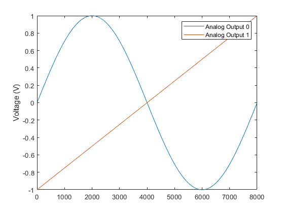
Generate two output signals (a 1 Hz sine wave and a 1 Hz ramp) and plot them. The plot depicts the data generated on both channels for a device that supports simultaneous sampling.
n = dq.Rate;
outputSignal1 = sin(linspace(0,2*pi,n)');
outputSignal2 = linspace(-1,1,n)';
outputSignal = [outputSignal1 outputSignal2];
plot(1:n, outputSignal);
ylabel("Voltage (V)");
legend("Analog Output 0", "Analog Output 1");

Write Data
Use write to generate the output waveforms.
write(dq, outputSignal)
