Map 5G Physical Channels and Signals to the Resource Grid
This example shows how to generate and map 5G New Radio (NR) physical channels and signals to the resource grid using 5G Toolbox™ features.
Introduction
This figure shows the link elements that are modeled in this example in the context of a 5G downlink link. These elements are:
Generation of a physical downlink shared channel (PDSCH) and its demodulation reference signal (DM-RS)
MIMO precoding and mapping of the PDSCH and PDSCH DM-RS to the resource grid
OFDM modulation

Carrier Configuration
Specify the number of transmit antennas and create a carrier configuration object. This object controls the size of the resource grid. For simplicity, use the default carrier configuration object.
nTxAnts = 4;
carrier = nrCarrierConfig
carrier =
  nrCarrierConfig with properties:

                NCellID: 1
      SubcarrierSpacing: 15
           CyclicPrefix: 'normal'
              NSizeGrid: 52
             NStartGrid: 0
                  NSlot: 0
                 NFrame: 0
    IntraCellGuardBands: [0x2 double]

   Read-only properties:
         SymbolsPerSlot: 14
       SlotsPerSubframe: 1
          SlotsPerFrame: 10
PDSCH and PDSCH DM-RS Configuration
Create a PDSCH configuration object. This object specifies PDSCH-related parameters. Specify 16-QAM modulation, two layers, and full band allocation. This configuration maps the PDSCH into a bandwidth part (BWP) of equal size to the carrier. You can also use this object to specify other time-allocation parameters and DM-RS settings.
pdsch = nrPDSCHConfig;
pdsch.Modulation = "16QAM";
pdsch.NumLayers = 2;
pdsch.PRBSet = 0:carrier.NSizeGrid-1; % Full band allocation
Display the PDSCH and PDSCH DM-RS parameters.
pdsch
pdsch =
  nrPDSCHConfig with properties:

                NSizeBWP: []
               NStartBWP: []
             ReservedPRB: {[1x1 nrPDSCHReservedConfig]}
              ReservedRE: []
              Modulation: '16QAM'
               NumLayers: 2
             MappingType: 'A'
        SymbolAllocation: [0 14]
                  PRBSet: [0 1 2 3 4 5 6 7 8 9 10 11 12 13 14 15 16 17 18 19 20 21 22 23 24 25 26 27 28 29 30 31 32 33 34 35 36 37 38 39 40 41 42 43 44 45 46 47 48 49 50 51]
              PRBSetType: 'VRB'
    VRBToPRBInterleaving: 0
           VRBBundleSize: 2
                     NID: []
                    RNTI: 1
                    DMRS: [1x1 nrPDSCHDMRSConfig]
              EnablePTRS: 0
                    PTRS: [1x1 nrPDSCHPTRSConfig]

   Read-only properties:
            NumCodewords: 1
pdsch.DMRS
ans =
  nrPDSCHDMRSConfig with properties:

      DMRSConfigurationType: 1
         DMRSReferencePoint: 'CRB0'
          DMRSTypeAPosition: 2
     DMRSAdditionalPosition: 0
                 DMRSLength: 1
            CustomSymbolSet: []
                DMRSPortSet: []
                   NIDNSCID: []
                      NSCID: 0
    NumCDMGroupsWithoutData: 2
            DMRSDownlinkR16: 0

   Read-only properties:
                  CDMGroups: [0 0]
                DeltaShifts: [0 0]
           FrequencyWeights: [2x2 double]
                TimeWeights: [2x2 double]
    DMRSSubcarrierLocations: [6x2 double]
                 CDMLengths: [2 1]
PDSCH Generation
Generate indices to map the PDSCH to the grid.
[pdschIndices,pdschInfo] = nrPDSCHIndices(carrier,pdsch);
Generate and map random PDSCH bits to PDSCH symbols. The input argument pdschInfo.G specifies the bit capacity of the PDSCH, which is the length of the codeword from the channel coding stages. pdschInfo.G takes into account the resource elements (REs) available for PDSCH transmission. For simplicity, this example does not include downlink shared channel (DL-SCH) modeling.
pdschBits = randi([0 1],pdschInfo.G,1);
Generate PDSCH symbols. The PDSCH symbols are stored in a matrix of size -by-, where is the number of symbols and is the number of layers.
pdschSymbols = nrPDSCH(carrier,pdsch,pdschBits);
size(pdschSymbols)
ans = 1×2

        8112           2
PDSCH DM-RS Generation
Generate DM-RS symbols and indices.
dmrsSymbols = nrPDSCHDMRS(carrier,pdsch);
dmrsIndices = nrPDSCHDMRSIndices(carrier,pdsch);
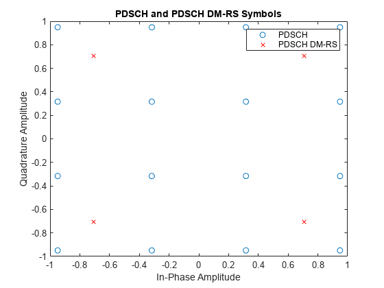
Display the constellation plot with the PDSCH and the PDSCH DM-RS symbols.
plot(pdschSymbols(:),"o");hold on
plot(dmrsSymbols(:),"xr");hold off
title("PDSCH and PDSCH DM-RS Symbols");xlabel("In-Phase Amplitude");ylabel("Quadrature Amplitude")
legend("PDSCH","PDSCH DM-RS")
MIMO Precoding and Mapping to the Resource Grid
Apply precoding. Channel measurements determine the precoding weights (also referred to as beamforming weights). However, this example does not model the propagation channel. This example assumes that the precoding weights are known.
% Precoding weights
W = fft(eye(nTxAnts))/sqrt(nTxAnts);              % Unitary precoding matrix
w = W(1:pdsch.NumLayers,:)/sqrt(pdsch.NumLayers); % Normalize by number of layers
The precoding matrix, w, must be a matrix of size -by-, where is the number of layers and is the number of transmit antennas.
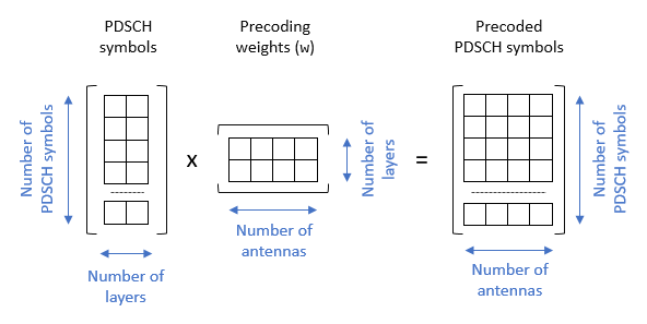
size(pdschSymbols)
ans = 1×2

        8112           2
size(w)
ans = 1×2

     2     4
Precode the PDSCH symbols.
pdschSymbolsPrecoded = pdschSymbols*w;
The number of rows in the pdschSymbolsPrecoded matrix corresponds to the number of PDSCH symbols and the number of columns corresponds to the number of antennas.
size(pdschSymbolsPrecoded)
ans = 1×2

        8112           4
Generate an empty resource grid. This grid spans one slot.
pdschGrid = nrResourceGrid(carrier,nTxAnts);
When you map the PDSCH symbols to the resource grid, take into account that the PDSCH indices generated by the nrPDSCHIndices function refer to layers and not antennas. This format can be useful when you map PDSCH symbols directly to layers. In this case, the resulting resource grids are not precoded.
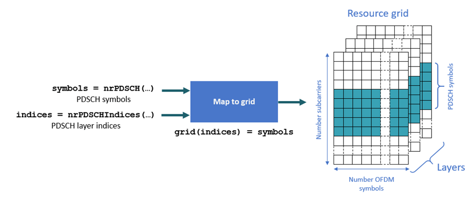
Because this example applies precoding to the PDSCH symbols before mapping to the resource grid, the precoded PDSCH symbols are mapped to antennas and not layers. To convert layer indices to antenna indices, use the nrExtractResources function.
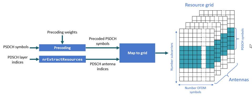
[~,pdschAntIndices] = nrExtractResources(pdschIndices,pdschGrid);
pdschGrid(pdschAntIndices) = pdschSymbolsPrecoded;
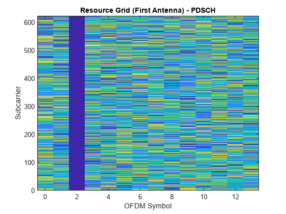
Display the resource grid for the first antenna. The blue gap is left for the DM-RS.
imagesc([0 carrier.SymbolsPerSlot-1],[0 carrier.NSizeGrid*12-1],abs(pdschGrid(:,:,1)));
axis xy;title("Resource Grid (First Antenna) - PDSCH");xlabel("OFDM Symbol");ylabel("Subcarrier")
Precode and map the DM-RS symbols to the grid. Similar to the PDSCH indices, the DM-RS indices refer to layers. To convert these layers to multiantenna indices, use the nrExtractResources function again.
% PDSCH DM-RS precoding and mapping
for p = 1:size(dmrsSymbols,2)
    [~,dmrsAntIndices] = nrExtractResources(dmrsIndices(:,p),pdschGrid);
    pdschGrid(dmrsAntIndices) = pdschGrid(dmrsAntIndices) + dmrsSymbols(:,p)*w(p,:);
end
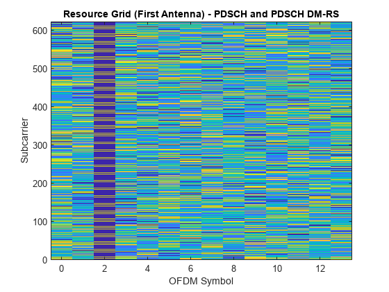
Display the resource grid for the first antenna.
imagesc([0 carrier.SymbolsPerSlot-1],[0 carrier.NSizeGrid*12-1],abs(pdschGrid(:,:,1)));
axis xy;title("Resource Grid (First Antenna) - PDSCH and PDSCH DM-RS");
    xlabel("OFDM Symbol");ylabel("Subcarrier")
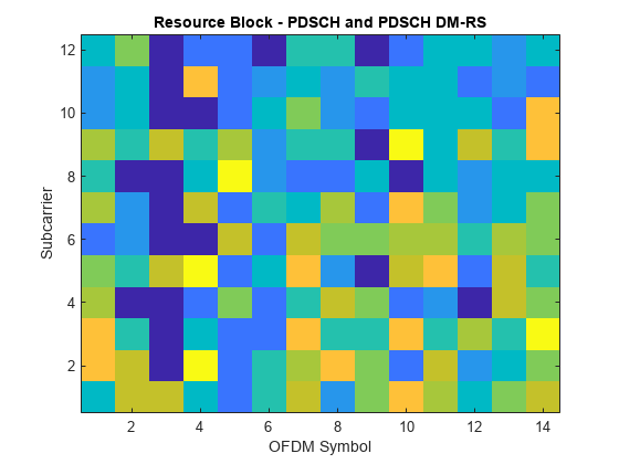
Display a single resource block (RB) from the resource grid. This view zooms into a single RB and provides a detailed view of the RE contents.
imagesc(abs(pdschGrid(1:12,:,1)));view(2)
axis xy;title("Resource Block - PDSCH and PDSCH DM-RS");ylabel("Subcarrier");xlabel("OFDM Symbol")
OFDM Modulation
OFDM-modulate the resource grid and display the time-domain waveform for the first antenna.
[txWaveform,waveformInfo] = nrOFDMModulate(carrier,pdschGrid);
plot(abs(txWaveform(:,1)));title("Time Domain Waveform (First Antenna)");xlabel("Sample Number");ylabel("Magnitude")
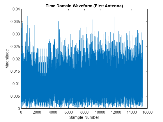
The waveformInfo output contains information about the time-domain waveform, such as the sampling rate.
waveformInfo
waveformInfo = struct with fields:
                   Nfft: 1024
             SampleRate: 15360000
    CyclicPrefixLengths: [80 72 72 72 72 72 72 80 72 72 72 72 72 72]
          SymbolLengths: [1104 1096 1096 1096 1096 1096 1096 1104 1096 1096 1096 1096 1096 1096]
              Windowing: 36
           SymbolPhases: [0 0 0 0 0 0 0 0 0 0 0 0 0 0]
         SymbolsPerSlot: 14
       SlotsPerSubframe: 1
          SlotsPerFrame: 10
