Model PEM fuel cells with Simulink and Simscape
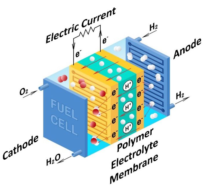
A fuel cell is an electrochemical system that uses reactants to produce electricity. A polymer electrolyte membrane (PEM) fuel cell is a popular technology that uses a chemical reaction involving hydrogen and oxygen to produce electricity and water as byproducts. PEM fuel cells incorporate a semipermeable membrane that allows proton transport and blocks the electron flow. Because of this characteristic, this kind of fuel cell is also known as a proton-exchange membrane fuel cell. As shown below, hydrogen enters the fuel cell at the anode and splits into protons and electrons. The protons pass through the membrane while the electrons flow through an external circuit, producing an electric current. Oxygen entering the fuel cell at the cathode end combines with the protons and electrons to produce water and heat.
PEM fuel cells are valued because of their low operating temperatures and pressures relative to other kinds of fuel cells. For these reasons, the technology is popular for use in electric vehicles as an alternative or supplement to battery systems. PEM fuel cells are used for stationary electricity production and are considered as part of a green energy storage-delivery system when combined with an electrolyzer and a renewable power source.
To use simulation to develop applications employing fuel cells, engineers need models of different fidelities. These scenarios include:
- Assessing the temperature and electrical performance of the fuel cell stack using a fuel cell model that describes the electrochemical reaction.
- Optimizing range, performance, and thermal effects of a fuel cell electric vehicle using a less detailed system-level fuel cell model.
- Developing and optimizing a fuel cell control system using a fuel cell model suitable for hardware-in-the-loop testing.
- Designing and simulating electrical generation systems using a fuel cell model with functional details for component and balance-of-plant sizing.
- Performing economic feasibility of hydrogen generation and power output using fuel cell and electrolyzer models.
Simscape™ and Simscape Electrical™ provide model libraries for simulating fuel cells. Engineers can use these models for developing fuel cell control systems and analyzing fuel cells as an electricity source as part of an electrical system. Used with Simulink®, these models support fuel cell control system development for electric vehicles that includes closed-loop design and control logic. Engineers can generate code from these fuel cell models for validation and production with support for AUTOSAR and certification workflows to achieve functionalities like current, voltage, and power monitoring and thermal management.
For engineers interested in building a model of a fuel cell stack, the Simscape Electrical fuel cell model provides two levels of fidelity. A simplified fuel cell model provides the Nernst voltage at the nominal condition of temperature and pressure. A more detailed fuel cell model outputs the Nernst voltage based on input signals of pressures and flow rates of fuel and air. Both models let engineers assess voltage-current characteristics and heat generation.
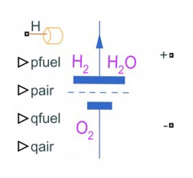
Simscape Electrical fuel cell model.
With Simscape, engineers can customize a complete PEM fuel cell model. This includes the fuel cell stack and balance-of-plant components such as air compressors, humidifiers, hydrogen recirculation paths, cooling systems, and water management. This first-principles–based fuel cell model using electrochemistry enables development of a PEM fuel cell at both the component and system levels. This level of fuel cell model detail lets engineers model functionalities like current, voltage, and power monitoring and thermal management.
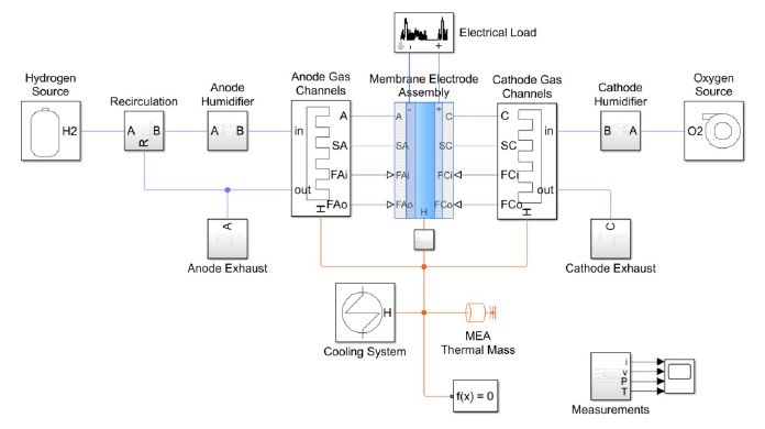
Simscape PEM fuel cell system model.
A fuel cell model as part of an electrical system provides a framework for performing trade studies to economize fuel cell stack efficiency, hydrogen and oxygen utilization, and fuel and air consumption.
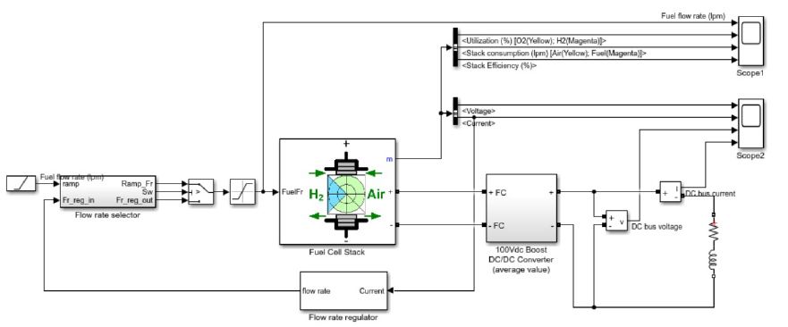
Simscape Electrical 6 kW fuel cell model.
As shown in Powertrain Blockset™, a PEM fuel cell model with electrochemical reactions, hydrogen and air handling, and thermal management systems, can be combined with a battery system and electric motor to model the powertrain of a fuel cell virtual vehicle.
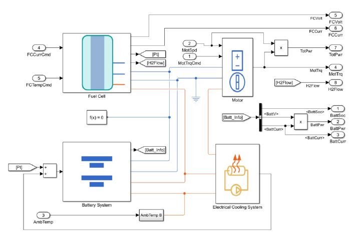
Fuel cell model and battery system model for an electric vehicle.
Examples and How To
Customer Stories
See also: Simscape Electrical, Powertrain Blockset, MATLAB and Simulink for electric vehicle development, Simulink for Electrification, MATLAB and Simulink Based Books for fuel cell development, what is a hydrogen electrolyzer?
