3T Develops Robot Emergency Braking System with Model-Based Design
Challenge
Design and implement a robot emergency braking system with minimal hardware testing
Solution
Use Model-Based Design with Simulink and HDL Coder to model, verify, and implement the controller
Results
- Cleanroom time reduced from weeks to days
- Late requirement changes rapidly implemented
- Complex bug resolved in one day
“With Simulink and HDL Coder we eliminated programming errors and automated delay balancing, pipelining, and other tedious and error-prone tasks. As a result, we were able to easily and quickly implement change requests from our customer and reduce time-to-market.”

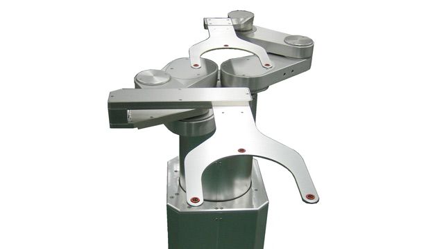
A SCARA robot.
Selective Compliance Assembly Robot Arm (SCARA) assemblies are widely used in semiconductor manufacturing because they excel at performing motions in a horizontal plane, where most wafer-handling movements take place. Like any high-voltage machinery moving at high speeds, SCARA robots can cause significant damage to their own components and to surrounding machines if they malfunction. To help prevent such an occurrence, engineers at 3T designed an emergency braking system for SCARA robots.
When the project began, the team at 3T did not know whether a braking system could be designed to stop the robot in time to prevent a collision without damage to the robot itself. 3T engineers used Model-Based Design with MATLAB® and Simulink® to conduct a feasibility study, identify a solution, and implement a real-time braking system controller on an FPGA.
“Model-Based Design enabled us to quickly try different control approaches to see what would work and what would not,” says Ronald van der Meer, systems engineer at 3T. “To minimize hardware testing and debugging in the cleanroom, we tested and refined our solution via simulation in Simulink and then used code generation with HDL Coder to implement it once it was verified.”
Challenge
3T’s customer, a leading Dutch producer of semiconductor manufacturing equipment, had stringent requirements for the braking system. To prevent potentially disastrous collisions, the control system would have to stop the robot with millimeter accuracy in less than 0.5 seconds without causing damage to the robot. At the outset, neither 3T nor its customer knew if it was possible to design a braking system that met these requirements.
Testing in the cleanroom and working with a real machine or prototype is expensive. Furthermore, testing the braking system on real hardware could damage the costly equipment. For this reason, the 3T engineers needed to verify the braking design before the initial hardware implementation. They recognized that writing VHDL® code by hand, as they had on previous projects, would require them to spend too much time testing and debugging in the cleanroom late in the project.
Solution
3T used Model-Based Design with MATLAB, Simulink, and HDL Coder™ to design and implement the SCARA emergency braking system controller.
The semiconductor manufacturer provided the 3T engineering team with a mechanical model of the robot created in Simulink.
The 3T team complemented this mechanical model with two additional models: a basic controller model, created with Simulink, and a model of the electronics, created with Simscape Electrical™. They then simulated the complete system model and shared the model and initial simulation results with the customer. This exchange provided an opportunity for the customer to improve the mechanical model and suggest enhancements to the controller.
The 3T team continued to improve and refine the controller model in Simulink, simulating dozens of scenarios and parameter sensitivities until they had confirmed the feasibility of the design.
Since most FPGAs operate most efficiently using fixed-point implementations of control algorithms, the team developed a fixed-point representation of their controller model, using Fixed-Point Designer™ to guide decisions on word lengths and scaling.
The team then replaced the floating-point controller model in the system model with the fixed-point version using model referencing in Simulink and verified the fixed-point implementation using simulation.
They generated algorithmic VHDL code from the fixed-point controller model with HDL Coder.
Using HDL Verifier™, they integrated a third-party IP core from the FPGA vendor into their design and generated a test bench for verification of the VHDL code using Mentor Graphics® ModelSim®.
Following initial hardware tests, the team refined the model, ran additional simulations to test the modifications, and regenerated VHDL code for the final braking system, which the customer is now using in production.
3T engineers are now completing similar projects using Model-Based Design with MINT, the company’s new SoC multi-interface development board, for rapid prototyping and hardware-in-the-loop testing.
Results
- Cleanroom time reduced from weeks to days. “With Model-Based Design we verified much of our design early in development and then generated defect-free VHDL,” says van der Meer. “As a result, instead of weeks, we needed only a few days in the cleanroom. The braking system needed only minor tweaks because it was almost spot-on the first time we tested it.”
- Late requirement changes rapidly implemented. “During final tests, a new requirement arose that limited maximum deceleration,” says van der Meer. “In Simulink we found a way to address this requirement using pulse-width modulation. Simulink and HDL Coder enabled us to implement a solution in a matter of days and prevent the project from heading toward failure.”
- Complex bug resolved in one day. “We encountered one nasty design logic bug that could easily have taken weeks, if not months, to identify and fix,” says van der Meer. “We quickly diagnosed the problem by analyzing logged data in MATLAB and replaying this data in Simulink simulations. We implemented a fix in the model, regenerated the VHDL, and had an updated version ready the next day.”