Estimating the Frequency Response of a Power Electronics Model
By Antonino Riccobono and Arkadiy Turevskiy, bat365
This article is the first in a three-part series. Part 2, Estimating the Frequency Response of a Power Electronic Model: Sinestream vs. Pseudo-Random Binary Sequence (PRBS), compares FRE for an open-loop buck converter with sinestream and with PRBS, focusing on estimation time, number of estimated frequency points, and estimation accuracy. Part 3, Cascade Digital PID Control Design for Power Electronics Models, describes a frequency-response-estimation based control design workflow for tuning the controller gains of a switch-mode buck converter with inner current control loop and outer voltage control loop.
Power electronics systems rely on feedback control to convert voltages and currents from the power source to those needed by the load. For example, a DC-DC power converter uses a control system to achieve the desired output voltage level and to maintain that level as the source voltage and load resistance change.
Power electronics engineers base their control designs on classic control theory. Since the theory is based on linear time-invariant (LTI) systems such as transfer functions and state-space models, to apply it to a power electronics system, engineers need to find an LTI representation of such a system.
Frequency response estimation (also known as an AC sweep) is commonly used to compute an LTI representation of a power electronics model. Frequency response estimation involves superimposing a small perturbation signal of controllable amplitude and frequency onto the input of the system operating in steady state and measuring the system response to this perturbation. Measured input and output signals can be then used to compute either the frequency response or a transfer function—that is, the LTI system that represents the system dynamics around the operating point.
This article describes a six-step workflow for estimating the frequency response of an open-loop boost converter.
The Open-Loop Boost Converter Model
A boost converter is a well-known switch-mode converter that is capable of producing a DC output voltage greater than the DC input voltage. It is used to connect a lower-voltage source to a higher-voltage load in many applications, including consumer electronics products, electric automobiles, more-electric ships and aircraft, renewables, and LED drivers.
Our switch-mode open-loop boost converter model is built with Simscape Electrical™ components (Figure 1). It is assumed that the converter operates in continuous conduction mode (CCM), which means that the inductor current never goes to zero when the converter is operating in steady state. The input perturbation and output measurement points for frequency response estimation are set for the duty cycle and output voltage, respectively. The control-to-output transfer function will then have the duty cycle as control input and the output voltage as output.
Frequency Response Estimation Workflow
The frequency response estimation workflow involves the following six steps.
1. Specify which portion of the model requires frequency response estimation.
To do this, we configure linearization analysis points that specify the inputs and outputs for estimation from the Linearization Manager app in Simulink Control Design™. We assign the input perturbation to the duty cycle and the output measurement to the output voltage (Figure 2).
2. Find an operating point and initialize the model.
To obtain a frequency response that accurately captures system dynamics, estimation should be performed at a steady-state operating point. The simulation results show that the boost converter reaches steady-state operation after roughly 0.005 seconds (Figure 3, left). We can take a simulation snapshot at 0.005 seconds to find the steady-state operating point (Figure 3, middle). At the end of the simulation, an OperatingPoint object is created in the app workspace. We can initialize the model to this object by clicking “Initialize model” (Figure 3, right). Note: It is important to ensure that there are no disturbances causing changes in the operating point during the perturbation injection.
3. Create a perturbation signal.
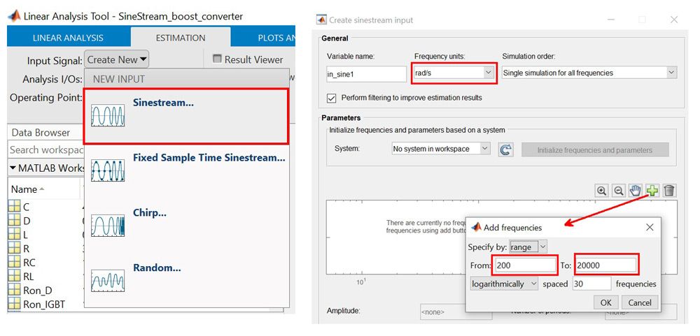
From the Model Linearizer app, we select sinestream as the perturbation signal. A sinestream signal consists of a sweep of sine waves that excites the system for a certain period. First, we specify the range of frequencies that the sine sweep should cover (Figure 4).
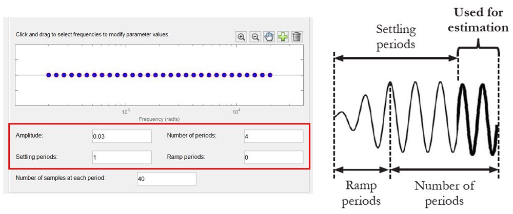
We can then specify amplitudes, number of periods, ramp periods, and settling periods, either for all the frequencies or for a subset (Figure 5).
4. Compute the non-parametric frequency response.
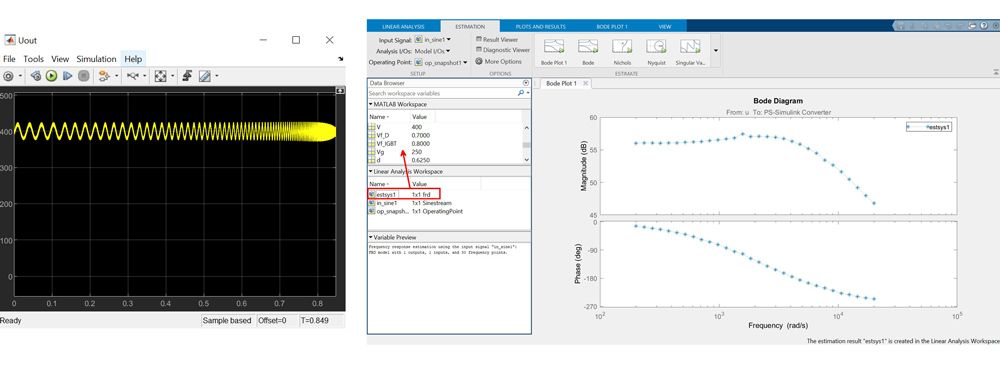
To start the computation, we click the “Estimate” button in the Estimate tab. While the simulation is running, Simulink Control Design injects the sinestream signal at the input we specified and measures the response at the output. At the end of the simulation an frd object is created in the app workspace. This object collects frequency response data—that is, the non-parametric model, a description of the system as discrete frequency points. Figure 6 shows the time-domain and frequency-domain results.
5. Obtain the parametric model
In this step we fit a transfer function to the data (extract the parametric model represented by an idtf object) using the tfest command in System Identification Toolbox™. To do so, we need to copy the identified frd object from the Linear Analysis workspace to the MATLAB workspace (red arrow in Figure 6). We can then use the tfest command either at the command line or in a script. Since the boost converter is a second-order system, the number of poles in tfest needs to be set to 2. If we do not know the order of a system for which we are estimating dynamics, we can try several different values for the number of poles and choose the lowest value that provides an acceptable fit.
6. Verify the results.
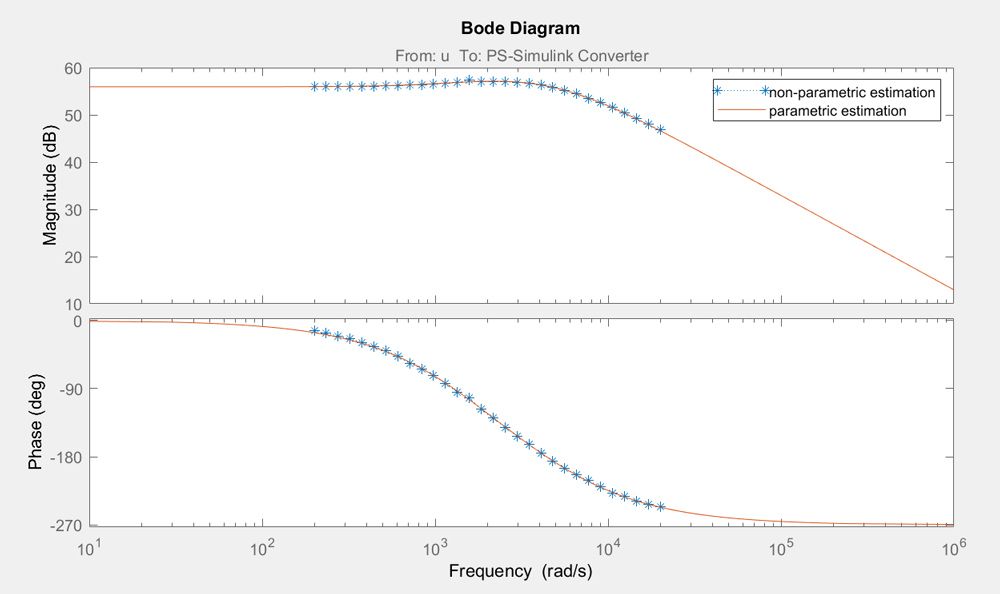
First, we verify the parametric and non-parametric estimations for the boost converter in CCM. Figure 7 shows that the two estimations are closely matched.
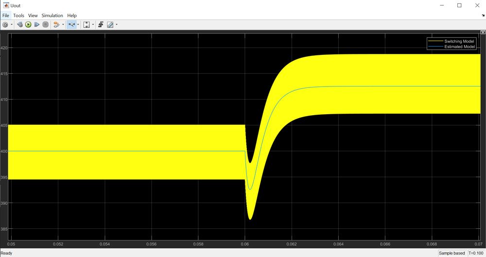
Next, we perform a time-domain verification in a Simulink® simulation with the switch-mode boost converter and a Transfer Function block implementing the parametric estimation. We measure and compare the response of both systems to the same small perturbation signal, that is, a 2% positive step superimposed on the steady-state duty cycle. Figure 8 shows that the estimated model response closely matches the switching model response, validating the estimation itself.
Now that we have a computed LTI representation of our boost converter model, we can use it for control design and analysis. Specifically, we can import the estimated LTI object into the PID Tuner app to tune the controller parameters to meet bandwidth, phase margin, and other feedback dynamic requirements.
Published 2020


