Using Statistics to Analyze Uncertainty in System Models
By Stuart Kozola, bat365 and Dan Doherty, bat365
Engineers and scientists rely on models to describe system behavior. System models are often created and analyzed under the assumption that the model inputs, defining parameters (constants), and operating environment are known precisely. Every real-world system operates under uncertainty, however, and failure to account for that uncertainty can lead to inaccurate predictions of system behavior.
Using a Simulink model of a DC motor as an example, this article describes tools and techniques in MATLAB and Statistics and Machine Learning Toolbox that let you quickly and easily analyze uncertainty in your system model and understand how it affects model performance.
DC Motor Model
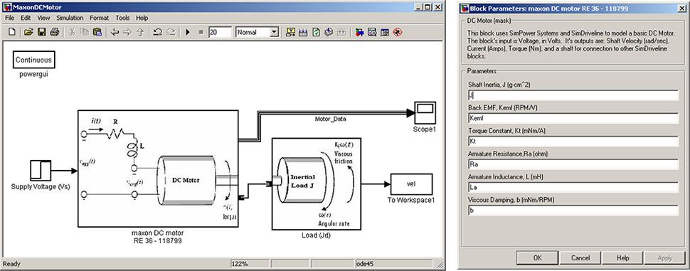
The DC motor model (Figure 1) has two inputs—the supply voltage (Vs) and the inertial load (Jd)—and six adjustable model parameters. These parameters, which were defined based upon manufacturer specifications for the motor, are assumed to be constant in our model.
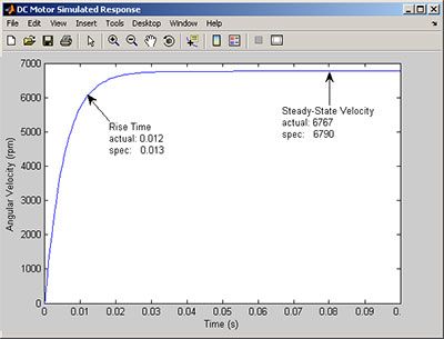
The output characteristics of interest are rise time and steady-state angular velocity (Figure 2). The model’s output is close to the manufacture’s specifications for this single operating condition, but how do we know that our model is accurate outside this single calibration point?
We must ensure that our model is accurate for the range of input conditions under which the motor will operate. To do this, we need to acquire experimental data from an actual motor over a representative set of operating conditions and then compare the results with results from simulating our model under the same input conditions.
Acquiring Experimental Data
We use Design of Experiments (DOE) to derive a minimal set of test points that covers the full range of input conditions. Before selecting an appropriate experimental design, we identify the factors, ranges, and levels that we wish to investigate, as follows:
| Factor | Range | Levels |
|---|---|---|
| Supply Voltage (Vs) | 12 – 36 V | 12, 24, 36 V |
| Inertial Load (Jd) | 0 – 0.005 kg m2 | 0.001, 0.003, 0.005 kg m2 |
Statistics and Machine Learning Toolbox provides several experimental design options. We choose a face-centered central composite design for this application. The command ccdesign generates a matrix of input combinations to test, where each row represents a separate test.
factorNames = {'Voltage','Inertial Load'};
noFactors = length(factorNames);
design = ccdesign(noFactors,'type','faced');
Figure 3 displays the test points within the design space. The center point (Vs = 24 V, Jd = 3 kg m2) is repeated 8 times to give us a way to estimate experimental error, resulting in a total of 16 test points.
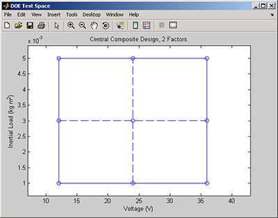
This designed experiment assumes that a single test operator and single DC motor are to be tested. To account for potential differences across operators and motors, we repeat the experiment for three different motors tested by three different operators, resulting is a total of 9 tests.
We import our test data into MATLAB and store it using the dataset array in Statistics and Machine Learning Toolbox. Using the grpstats function, we calculate the mean and standard deviation for each test point (Figure 4).
testResults = dataset('XLSFile','testResults.xls');
byPt = grpstats(testResults,{'DOE_Point'},...
{@mean @std},'DataVars',{'RiseTime','SSVelocity'});
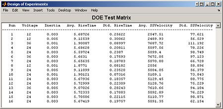
The average rise time and steady-state velocity values clearly differ among the 16 test points, which indicates that these values depend on voltage and inertial load inputs. The nonzero standard deviations show that there are differences across operators and motors. To test whether these differences are significant, we perform an analysis of variance (ANOVA) test across operators, motor, and inputs.
group = {ds.DOE_Vemf,ds.DOE_J,char(ds.Motor),char(ds.Operator)};
varNames = {'Voltage','Inertia','Motor','Operator'};
anovan(ds.RiseTime,group,1,3,varNames)
anovan(ds.SSVelocity,group,1,3,varNames)
Figure 5 shows the results of the ANOVA. The column on the far right in each table shows the p-value (Prob>F), a measure used to determine whether the variables listed under the Source column are significant. A p-value at or below 0.05 gives a 95% confidence that the source is significant. Our ANOVA results show that voltage and inertia have a significant effect on rise time and steady-state velocity, while differences across operators and motors are not significant.
Remember, the purpose of the designed experiment was to derive test points that would enable us to check how accurate our DC motor model is for the full range of input conditions. Now that we’ve acquired our experimental data and shown that it’s reliable (in other words, that differences across operators and motors are not significant), we will simulate the model and compare the simulation data to our test data.
Comparing Test and Simulation Data
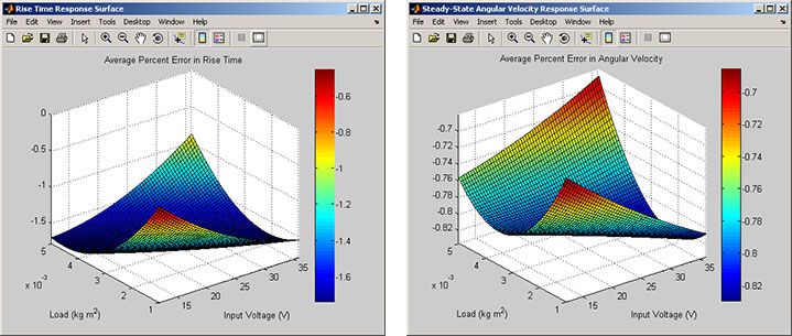
Figure 6 shows the average simulation error as a function of voltage and inertial load. These plots display the residual data as response surfaces, which we fitted using the regstats function from Statistics and Machine Learning Toolbox.
As Figure 6 shows, our model’s error is not constant across input conditions, and it does not average zero. Percent errors are relatively small, however, ranging from -0.5% to -1.8% for rise time and -0.68% to -0.82% for steady-state angular velocity, and are acceptable for our application. We could further reduce our model's error by fitting the model parameters to data using Simulink Parameter Estimation.
Based on our analysis so far, our model seems to be quite accurate, but how well does it represent a larger motor sample? Our ANOVA test suggested that motor-to-motor variations are not significant, but we only looked at three sample motors. In reality, thousands will be manufactured, and because of manufacturing tolerances and other factors, each will be slightly different. We need to perform a more thorough evaluation to determine whether our model is robust enough to accurately model all motors of this design.
Evaluating the Effect of Uncertainty in Model Parameters
To account for uncertainty in motor characteristics, we define the model’s parameters as distributions of values rather than as single fixed values. We then perform a Monte-Carlo simulation, running the model repeatedly with random combinations of parameter values.
Before we can run a Monte Carlo simulation, we must define our uncertain motor parameters. We use random number generators from Statistics and Machine Learning Toolbox to create 1,000 random samples for each parameter. Tolerances on the armature parameters (resistance, Ra, and inductance, La) are about 10%, and the torque constant (Kt) has an approximately 3% tolerance. We’ll assume that these parameters follow a normal distribution.
mcSamples = 1000;
mcRa   = normrnd(1.71,0.17/3,[mcSamples 1]);          % Armature Resistance
mcLa   = normrnd(0.3,.03/3,[mcSamples 1]);            % Armature Inductance
mcKt   = normrnd(44.5,1.33/3,[mcSamples 1]);          % Shaft Inertia
mcKemf = 30000/pi./mcKt;                              % Back EMF

mcJ = normrnd(65.2,0.70/3,[mcSamples 1]);             % shaft inertia
mcb = normrnd(7.1213e-7,7e-8/3,[mcSamples 1]);        % viscous damping
The input voltage and inertial load are defined as uniform distributions between their appropriate ranges to ensure that we cover the full design space.
 % Set input conditions to the motor:
mcV = unifrnd(12,36,[mcSamples 1]);
mcJd = unifrnd(0.001,0.005,[mcSamples 1]);
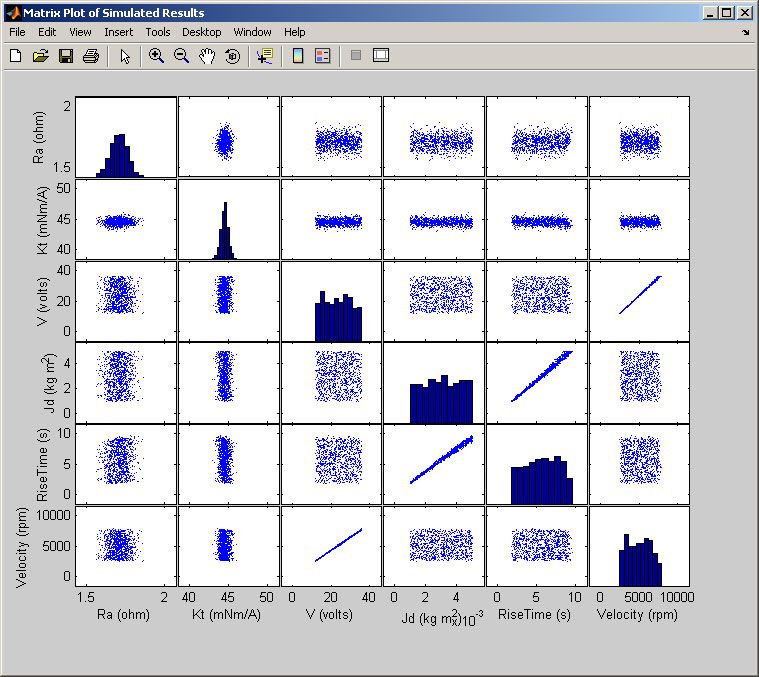
Figure 7 displays a matrix plot that summarizes results from the Monte Carlo simulation.
The diagonals show a histogram of model parameters and outputs, and the plots above and below the diagonal are useful for quickly finding trends between model parameters and outputs. Most of the plots do not indicate a strong trend—with the exception of input voltage on the steady-state velocity and inertial load on rise time. Both of these trends are approximately linear and show some scatter, which is a result of the uncertain motor parameters that we modeled in our simulation.
We want to determine whether our simulation scatter is consistent with the variation that we observed in our experiment. To do this, we overlay the experimental data gathered previously onto the simulation results (Figure 8).
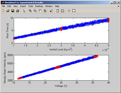
The scatter observed in the experiment appears to be consistent with the scatter observed in our simulation data. This indicates that our model can be used to accurately predict performance variability among motors.
Summary
Evaluating model accuracy and accounting for uncertain model parameters is an important part of the modeling process. It provides insight into the system’s operation and helps ensure that your model is accurate.
This article showed how MATLAB and Statistics and Machine Learning Toolbox can be used to analyze uncertainty in a DC motor model created in Simulink. We began by quantifying the accuracy of our model by comparing test and simulation data over the range of input conditions that we anticipated the motor would encounter. The results showed that our model predicted rise time and steady-state velocity with less than 2% error, which is accurate enough for our needs.
We then performed a Monte-Carlo simulation to see whether our model could accurately capture performance variability resulting from slight differences among motors. We concluded that our model reliably predicts performance variability among motors.
Published 2007
